
ESP32-Controlled Robotics Platform with Ultrasonic Sensors and GPS
View and Edit Project In Cirkit Designer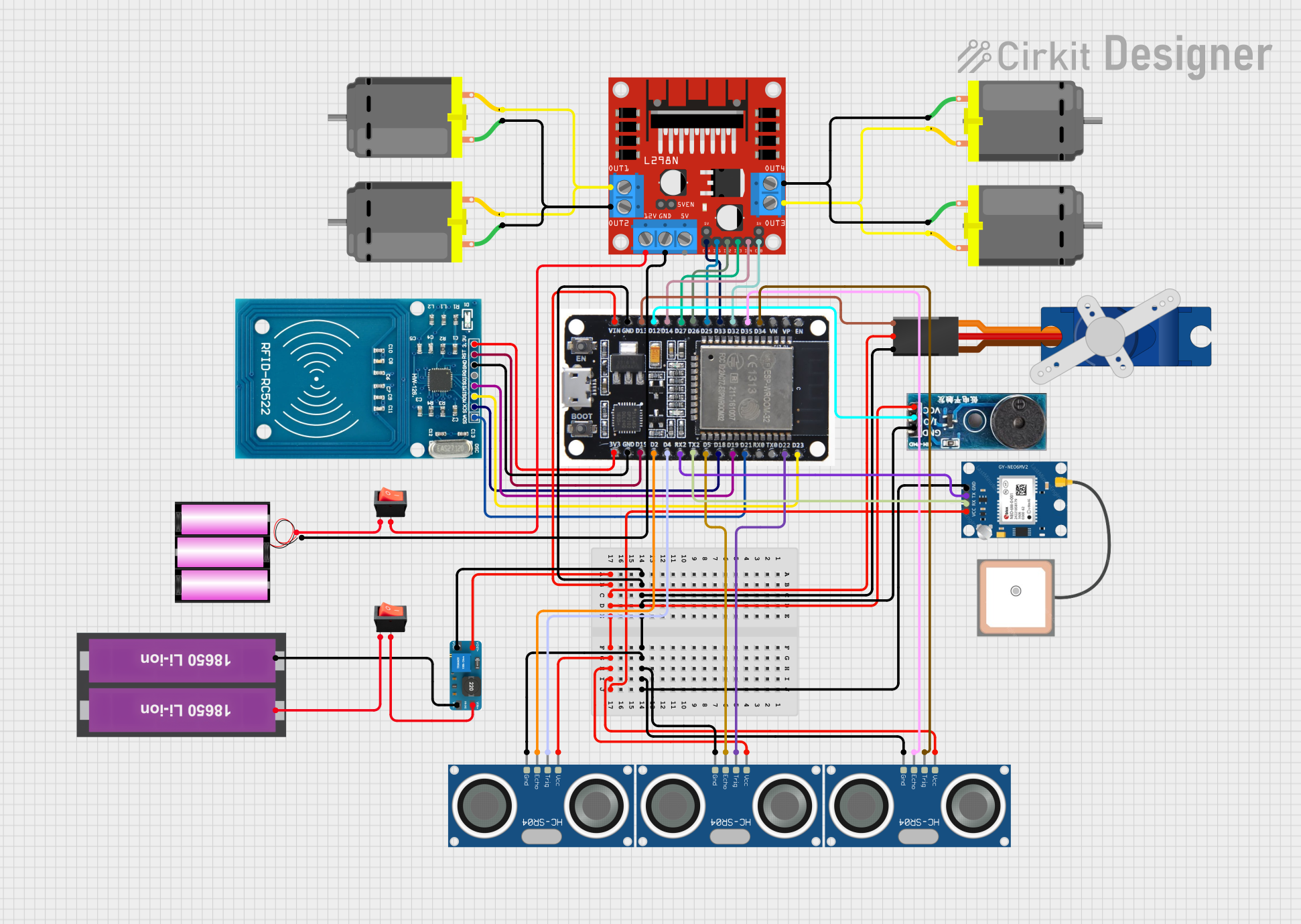
Circuit Documentation
Summary
This circuit is designed to control multiple DC motors using an ESP32 microcontroller and an L298N DC motor driver. It includes ultrasonic sensors (HC-SR04) for distance measurement, a GPS module (NEO 6M) for location tracking, an RFID reader (RC522) for identification tasks, a servo motor (Tower Pro SG90) for precise angular movement, and a buzzer module for audio feedback. Power management is handled by a 12V battery, a pair of 18650 Li-ion batteries, a DC to DC boost converter, and rocker switches for on/off control. The circuit is likely intended for a robotic vehicle with navigation and identification capabilities.
Component List
- ESP32: A microcontroller with Wi-Fi and Bluetooth capabilities, used as the main processing unit of the circuit.
- L298N DC Motor Driver: A module that allows the ESP32 to control the speed and direction of DC motors.
- DC Motors: Actuators that convert electrical energy into mechanical rotation.
- HC-SR04 Ultrasonic Sensors: Sensors that measure distance by emitting ultrasonic waves and measuring the time taken for the echo to return.
- Battery 12V: A power source for the motor driver and motors.
- 18650 Li-ion Batteries x 2: A power source for the ESP32 and other low-voltage components.
- Tower Pro SG90 Servo: A small servo motor for precise control of mechanical movement.
- Rocker Switches: Used to control the power supply to the circuit.
- RFID-RC522: An RFID reader module for reading RFID tags.
- Buzzer Module: An audio signaling device.
- GPS NEO 6M: A GPS module for obtaining geographical location data.
- DC to DC Boost Converter: A power converter that steps up the voltage from the Li-ion batteries to a higher voltage required by other components.
Wiring Details
ESP32
- GND: Connected to the ground pins of all components requiring a ground connection.
- VIN: Connected to the VCC pins of all components requiring 5V power.
- 3V3: Powers the RFID-RC522 module.
- D34: Connected to the TRIG pin of one HC-SR04 sensor.
- D35: Connected to the ECHO pin of the same HC-SR04 sensor.
- D32: Controls the ENB pin of the L298N motor driver.
- D33: Controls the ENA pin of the L298N motor driver.
- D25: Controls the IN1 pin of the L298N motor driver.
- D26: Controls the IN2 pin of the L298N motor driver.
- D27: Controls the IN3 pin of the L298N motor driver.
- D14: Controls the IN4 pin of the L298N motor driver.
- D12: Connected to the I/O pin of the Buzzer Module.
- D13: Connected to the Signal pin of the Tower Pro SG90 servo.
- D15: Connected to the RST pin of the RFID-RC522 module.
- D2: Connected to the ECHO pin of another HC-SR04 sensor.
- D4: Connected to the TRIG pin of the same HC-SR04 sensor.
- RX2: Receives data from the TX pin of the GPS NEO 6M module.
- TX2: Transmits data to the RX pin of the GPS NEO 6M module.
- D5: Connected to the ECHO pin of another HC-SR04 sensor.
- D18: Connected to the SCK pin of the RFID-RC522 module.
- D19: Connected to the MISO pin of the RFID-RC522 module.
- D21: Connected to the SDA pin of the RFID-RC522 module.
- D22: Connected to the TRIG pin of another HC-SR04 sensor.
- D23: Connected to the MOSI pin of the RFID-RC522 module.
L298N DC Motor Driver
- OUT1/OUT2: Connected to two DC motors.
- OUT3/OUT4: Connected to two other DC motors.
- 12V: Connected to the 12V battery through a rocker switch.
- GND: Connected to the ground of the 12V battery.
DC Motors
- Pin 1 & Pin 2: Connected to the OUT pins of the L298N motor driver.
HC-SR04 Ultrasonic Sensors
- VCC: Connected to the VIN of the ESP32.
- GND: Connected to the GND of the ESP32.
- TRIG: Connected to various GPIO pins on the ESP32 for triggering the ultrasonic pulse.
- ECHO: Connected to various GPIO pins on the ESP32 for receiving the echo pulse.
GPS NEO 6M
- VCC: Powered by the VIN of the ESP32.
- GND: Connected to the GND of the ESP32.
- RX: Connected to the TX2 pin of the ESP32.
- TX: Connected to the RX2 pin of the ESP32.
Tower Pro SG90 Servo
- Signal: Controlled by the D13 pin of the ESP32.
- +5V: Powered by the VIN of the ESP32.
- GND: Connected to the GND of the ESP32.
RFID-RC522
- VCC (3.3V): Powered by the 3V3 pin of the ESP32.
- RST: Controlled by the D15 pin of the ESP32.
- GND: Connected to the GND of the ESP32.
- IRQ: Not connected.
- MISO: Connected to the D19 pin of the ESP32.
- MOSI: Connected to the D23 pin of the ESP32.
- SCK: Connected to the D18 pin of the ESP32.
- SDA: Connected to the D21 pin of the ESP32.
Buzzer Module
- GND: Connected to the GND of the ESP32.
- Vcc: Powered by the VIN of the ESP32.
- I/O: Controlled by the D12 pin of the ESP32.
Power Management
- Battery 12V: Provides power to the L298N motor driver.
- 18650 Li-ion Batteries x 2: Provide power to the ESP32 and other components through the DC to DC boost converter.
- Rocker Switches: Used to control the power supply from the batteries.
- DC to DC Boost Converter: Steps up the voltage from the Li-ion batteries to power the ESP32 and other components.
Documented Code
No code was provided for the microcontrollers in the circuit. Therefore, this section is left blank until the relevant code is available for documentation.