Cirkit Designer
Your all-in-one circuit design IDE
Home /
Project Documentation
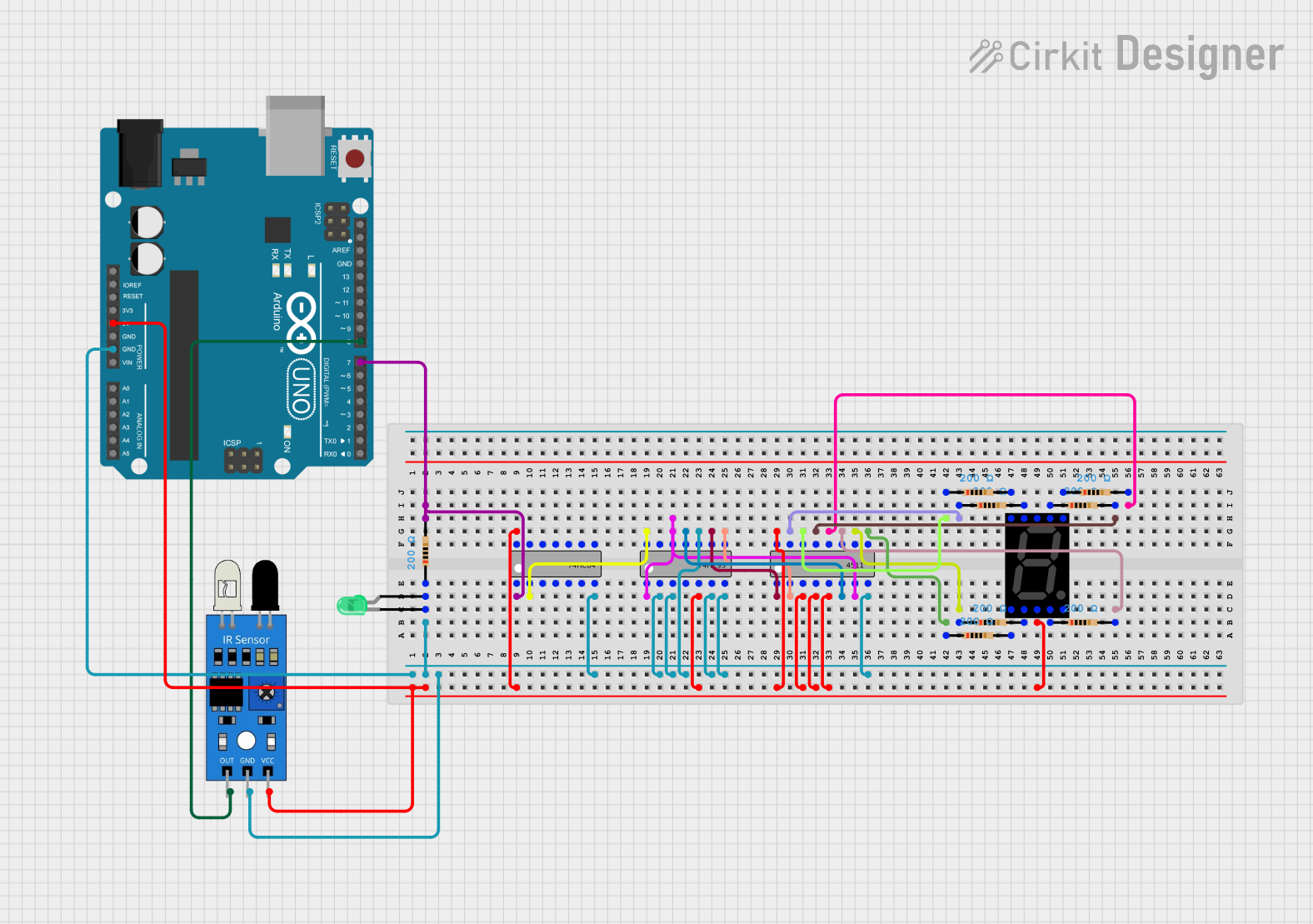
Arduino UNO-Based IR Sensor Counter with Seven Segment Display
Circuit Documentation
Summary
This circuit is designed to count objects detected by an IR sensor and display the count on a seven-segment display. The circuit uses an Arduino UNO to read the IR sensor and generate clock pulses for a counter IC. The counter output is then decoded and displayed on a seven-segment display.
Component List
Arduino UNO
- Description: Microcontroller board based on the ATmega328P.
- Pins: UNUSED, IOREF, Reset, 3.3V, 5V, GND, Vin, A0, A1, A2, A3, A4, A5, SCL, SDA, AREF, D13, D12, D11, D10, D9, D8, D7, D6, D5, D4, D3, D2, D1, D0
IR Sensor
- Description: Infrared sensor for object detection.
- Pins: out, gnd, vcc
74HC04
- Description: Hex Inverter IC.
- Pins: A1, Y1, A2, Y2, A3, Y3, GND, VCC, A6, Y6, A5, Y5, A4, Y4
74HC93
- Description: 4-bit Binary Counter IC.
- Pins: Clock 1, Reset 1, Reset 2, NC, VCC, Clock 0, Output 0, Output 3, GND, Output 1, Output 2
4511
- Description: BCD to 7-Segment Latch/Decoder/Driver.
- Pins: D1 (Input B), D2 (Input C), ~LT, ~BL, LE, D3 (Input D), D0 (Input A), GND, VCC, f, g, a, b, c, d, e
Resistor
- Description: Resistor with a resistance of 200 Ohms.
- Pins: pin1, pin2
Seven Segment Display (Wokwi Compatible)
- Description: Seven-segment display for numerical output.
- Pins: G, F, COM.2, B, A, E, D, COM.1, C, DP
LED: Two Pin (green)
- Description: Green LED.
- Pins: cathode, anode
Wiring Details
Arduino UNO
- GND: Connected to GND of 74HC04, 74HC93, 4511, IR Sensor, and Resistor (d2669fc2).
- 5V: Connected to VCC of 74HC04, 74HC93, 4511, Seven Segment Display (COM.1), and IR Sensor.
- D7: Connected to pin2 of Resistor (d2669fc2) and A1 of 74HC04.
- D8: Connected to out of IR Sensor.
IR Sensor
- out: Connected to D8 of Arduino UNO.
- gnd: Connected to GND of Arduino UNO.
- vcc: Connected to 5V of Arduino UNO.
74HC04
- A1: Connected to pin2 of Resistor (d2669fc2) and D7 of Arduino UNO.
- Y1: Connected to Clock 0 of 74HC93.
- GND: Connected to GND of Arduino UNO.
- VCC: Connected to 5V of Arduino UNO.
74HC93
- Clock 0: Connected to Y1 of 74HC04.
- Clock 1: Connected to D0 (Input A) of 4511.
- Reset 1: Connected to GND of Arduino UNO.
- Reset 2: Connected to GND of Arduino UNO.
- GND: Connected to GND of Arduino UNO.
- VCC: Connected to 5V of Arduino UNO.
- Output 0: Connected to D0 (Input A) of 4511.
- Output 1: Connected to D1 (Input B) of 4511.
- Output 2: Connected to D2 (Input C) of 4511.
- Output 3: Connected to D3 (Input D) of 4511.
4511
- D0 (Input A): Connected to Output 0 of 74HC93.
- D1 (Input B): Connected to Output 1 of 74HC93.
- D2 (Input C): Connected to Output 2 of 74HC93.
- D3 (Input D): Connected to Output 3 of 74HC93.
- GND: Connected to GND of Arduino UNO.
- VCC: Connected to 5V of Arduino UNO.
- ~LT: Connected to 5V of Arduino UNO.
- ~BL: Connected to 5V of Arduino UNO.
- LE: Connected to 5V of Arduino UNO.
- f: Connected to pin1 of Resistor (1e14dede).
- g: Connected to pin1 of Resistor (9d493389).
- a: Connected to pin2 of Resistor (e0210f7c).
- b: Connected to pin2 of Resistor (22cb4453).
- c: Connected to pin2 of Resistor (a7d30f7a).
- d: Connected to pin1 of Resistor (7c5abf49).
- e: Connected to pin1 of Resistor (4ad2ff8f).
Resistors
- Resistor (d2669fc2):
- pin1: Connected to cathode of LED.
- pin2: Connected to A1 of 74HC04 and D7 of Arduino UNO.
- Resistor (1e14dede):
- pin1: Connected to f of 4511.
- pin2: Connected to F of Seven Segment Display.
- Resistor (9d493389):
- pin1: Connected to g of 4511.
- pin2: Connected to G of Seven Segment Display.
- Resistor (e0210f7c):
- pin1: Connected to a of 4511.
- pin2: Connected to A of Seven Segment Display.
- Resistor (22cb4453):
- pin1: Connected to b of 4511.
- pin2: Connected to B of Seven Segment Display.
- Resistor (a7d30f7a):
- pin1: Connected to c of 4511.
- pin2: Connected to C of Seven Segment Display.
- Resistor (7c5abf49):
- pin1: Connected to d of 4511.
- pin2: Connected to D of Seven Segment Display.
- Resistor (4ad2ff8f):
- pin1: Connected to e of 4511.
- pin2: Connected to E of Seven Segment Display.
Seven Segment Display (Wokwi Compatible)
- G: Connected to pin2 of Resistor (9d493389).
- F: Connected to pin2 of Resistor (1e14dede).
- COM.1: Connected to 5V of Arduino UNO.
- B: Connected to pin1 of Resistor (22cb4453).
- A: Connected to pin1 of Resistor (e0210f7c).
- E: Connected to pin2 of Resistor (4ad2ff8f).
- D: Connected to pin2 of Resistor (7c5abf49).
- C: Connected to pin1 of Resistor (a7d30f7a).
LED: Two Pin (green)
- cathode: Connected to pin1 of Resistor (d2669fc2).
- anode: Connected to pin1 of Resistor (d2669fc2).
Code Documentation
Arduino UNO Code
const int IR_SENSOR_PIN = 8;  // Pin sensor IR
const int CLOCK_PIN = 7;      // Pin untuk clock pulse

// Variabel
int counter = 0;              // Hitungan counter dari 0-9
bool lastObstacleState = false; // Status deteksi sebelumnya
unsigned long debounceDelay = 50; // Waktu untuk mengatasi bouncing
unsigned long lastDebounceTime = 0; // Waktu terakhir bouncing terjadi

void setup() {
  // Inisialisasi pin
  pinMode(IR_SENSOR_PIN, INPUT);
  pinMode(CLOCK_PIN, OUTPUT);

  // Mulai dengan clock rendah
  digitalWrite(CLOCK_PIN, LOW);
}

void loop() {
  // Baca sensor IR (LOW saat ada objek terdeteksi)
  bool obstacleDetected = (digitalRead(IR_SENSOR_PIN) == LOW);

  // Waktu sekarang
  unsigned long currentTime = millis();

  // Jika ini adalah deteksi baru dan