Arduino UNO Based Health Monitoring System with I2C LCD and mlx90614 Infrared Thermometer
Circuit Documentation
Summary
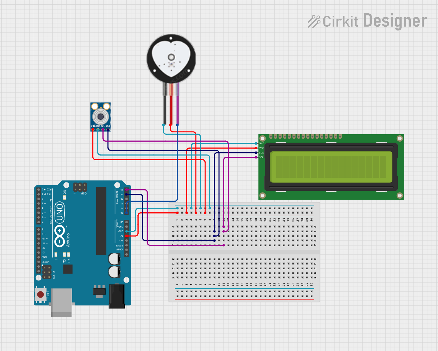
The circuit in question is designed around an Arduino UNO microcontroller, which serves as the central processing unit. The circuit includes a 16x2 I2C LCD for display purposes, an mlx90614 infrared temperature sensor for measuring temperature without contact, and a Heart Pulse Sensor for detecting heartbeats. The Arduino UNO is responsible for interfacing with these sensors, processing their data, and displaying relevant information on the LCD. Power distribution is managed through the 5V and GND pins of the Arduino, which are connected to the corresponding power pins of the other components. Communication with the mlx90614 and the 16x2 I2C LCD is facilitated via the I2C protocol, using the SDA and SCL lines.
Component List
Arduino UNO
- Description: A microcontroller board based on the ATmega328P.
- Pins: UNUSED, IOREF, Reset, 3.3V, 5V, GND, Vin, A0-A5, SCL, SDA, AREF, D0-D13.
- Purpose: Acts as the central processing unit for the circuit, interfacing with sensors and the LCD, and executing the embedded code.
16x2 I2C LCD
- Description: A 16-character by 2-line display with an I2C interface.
- Pins: GND, VCC, SDA, SCL.
- Purpose: Displays information processed by the Arduino UNO.
mlx90614 Infrared Temperature Sensor
- Description: A contactless infrared temperature sensor.
- Pins: SDA, SCL, GND, VIN.
- Purpose: Measures temperature without direct contact and sends data to the Arduino UNO.
Heart Pulse Sensor
- Description: A sensor that detects heartbeats.
- Pins: GND, VCC, SIGNAL.
- Purpose: Monitors heart pulse rate and sends the signal to the Arduino UNO.
Wiring Details
Arduino UNO
- 5V: Powers the 16x2 I2C LCD, mlx90614, and Heart Pulse Sensor.
- GND: Common ground for the 16x2 I2C LCD, mlx90614, and Heart Pulse Sensor.
- A4 (SDA): I2C data line connected to the mlx90614 and 16x2 I2C LCD.
- A5 (SCL): I2C clock line connected to the mlx90614 and 16x2 I2C LCD.
- A0: Analog input connected to the SIGNAL pin of the Heart Pulse Sensor.
16x2 I2C LCD
- GND: Connected to the Arduino UNO's GND.
- VCC: Powered by the Arduino UNO's 5V.
- SDA: Connected to the Arduino UNO's A4 pin.
- SCL: Connected to the Arduino UNO's A5 pin.
mlx90614 Infrared Temperature Sensor
- SDA: Connected to the Arduino UNO's A4 pin.
- SCL: Connected to the Arduino UNO's A5 pin.
- GND: Connected to the Arduino UNO's GND.
- VIN: Powered by the Arduino UNO's 5V.
Heart Pulse Sensor
- GND: Connected to the Arduino UNO's GND.
- VCC: Powered by the Arduino UNO's 5V.
- SIGNAL: Connected to the Arduino UNO's A0 pin.
Documented Code
Arduino UNO Code (sketch.ino)
void setup() {
  // put your setup code here, to run once:

}

void loop() {
  // put your main code here, to run repeatedly:

}
Note: The provided code is a template and does not contain any functional code. It is expected that the user will fill in the setup and loop functions with code to initialize the components and handle the main logic of the circuit, respectively.