
Arduino and ESP32-CAM Based Smart Traffic Light System with Car Detection
View and Edit Project In Cirkit Designer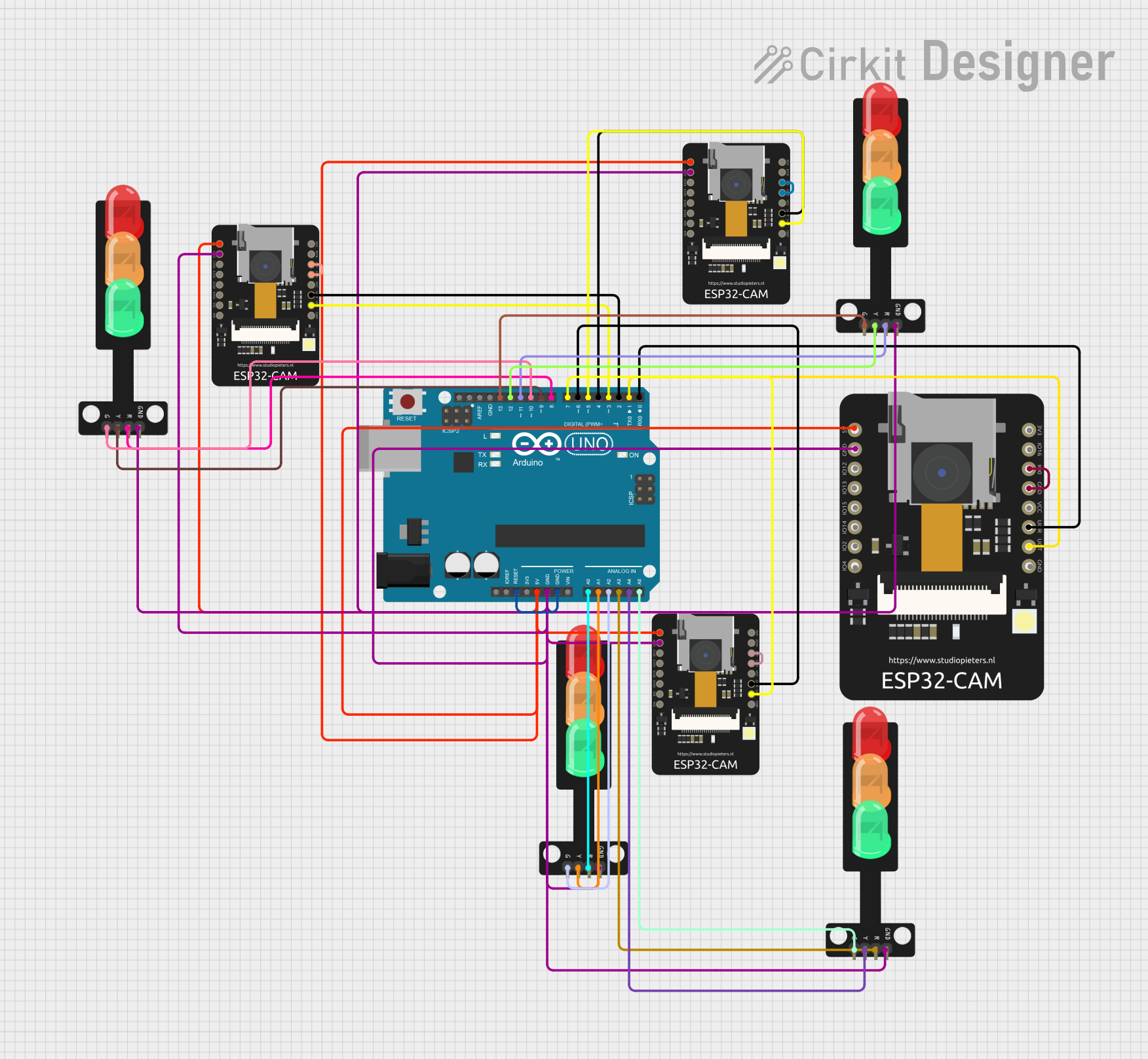
Circuit Documentation
Summary
This circuit is designed to manage a traffic light system using an Arduino UNO and multiple ESP32-CAM modules. The Arduino UNO controls four traffic lights, each with red, yellow, and green LEDs. The ESP32-CAM modules are used to monitor car counts in four different lanes. Based on the car counts, the Arduino UNO determines which lane should have the green light to optimize traffic flow.
Component List
Arduino UNO
- Description: A microcontroller board based on the ATmega328P.
- Pins: UNUSED, IOREF, Reset, 3.3V, 5V, GND, Vin, A0, A1, A2, A3, A4, A5, SCL, SDA, AREF, D13, D12, D11, D10, D9, D8, D7, D6, D5, D4, D3, D2, D1, D0
ESP32 CAM
- Description: A low-cost microcontroller with integrated Wi-Fi and Bluetooth, used for image processing and streaming.
- Pins: 5V, GND, GPIO12, GPIO13, GPIO15, GPIO14, GPIO2, GPIO4, 3.3V, GPIO16, GPIO0, 3.3V / 5V / P_OUT, GPIO3 / RX, GPIO1 / TX
ESP32 - CAM
- Description: Similar to the ESP32 CAM, used for image processing and streaming.
- Pins: 5V, GND, IO12, IO13, IO15, IO14, IO2, IO4, VOT, VOR, VCC, IO0, IO16, 3V3
Traffic Light
- Description: A module representing a traffic light with red, yellow, and green LEDs.
- Pins: Green, Yellow, Red, GND
Wiring Details
Arduino UNO
- Reset connected to GND.
- 5V connected to:
- 5V of ESP32 CAM.
- 5V of ESP32 - CAM (multiple instances).
- GND connected to:
- GND of ESP32 CAM.
- GND of ESP32 - CAM (multiple instances).
- GND of Traffic Light (multiple instances).
- A0 connected to Red of Traffic Light.
- A1 connected to Yellow of Traffic Light.
- A2 connected to Green of Traffic Light.
- A3 connected to Red of another Traffic Light.
- A4 connected to Yellow of another Traffic Light.
- A5 connected to Green of another Traffic Light.
- D13 connected to Green of another Traffic Light.
- D12 connected to Yellow of another Traffic Light.
- D11 connected to Red of another Traffic Light.
- D10 connected to Green of another Traffic Light.
- D9 connected to Yellow of another Traffic Light.
- D8 connected to Red of another Traffic Light.
- D7 connected to VOT of ESP32 - CAM.
- D6 connected to VOR of ESP32 - CAM.
- D5 connected to VOT of another ESP32 - CAM.
- D4 connected to VOR of another ESP32 - CAM.
- D3 connected to VOT of another ESP32 - CAM.
- D2 connected to VOR of another ESP32 - CAM.
- D1 connected to GPIO1 / TX of ESP32 CAM.
- D0 connected to GPIO3 / RX of ESP32 CAM.
ESP32 CAM
- 5V connected to 5V of Arduino UNO.
- GND connected to GND of Arduino UNO.
- GPIO1 / TX connected to D1 of Arduino UNO.
- GPIO3 / RX connected to D0 of Arduino UNO.
- GPIO0 connected to GND of ESP32 CAM.
ESP32 - CAM (multiple instances)
- 5V connected to 5V of Arduino UNO.
- GND connected to GND of Arduino UNO.
- VOT connected to:
- D7 of Arduino UNO.
- D5 of Arduino UNO.
- D3 of Arduino UNO.
- VOR connected to:
- D6 of Arduino UNO.
- D4 of Arduino UNO.
- D2 of Arduino UNO.
- IO0 connected to GND of ESP32 - CAM.
Traffic Light (multiple instances)
- GND connected to GND of Arduino UNO.
- Red connected to:
- A0 of Arduino UNO.
- A3 of Arduino UNO.
- D11 of Arduino UNO.
- D8 of Arduino UNO.
- Yellow connected to:
- A1 of Arduino UNO.
- A4 of Arduino UNO.
- D12 of Arduino UNO.
- D9 of Arduino UNO.
- Green connected to:
- A2 of Arduino UNO.
- A5 of Arduino UNO.
- D13 of Arduino UNO.
- D10 of Arduino UNO.
Code Documentation
#include <SoftwareSerial.h>

// Define SoftwareSerial for each ESP32-CAM
SoftwareSerial esp1(0, 1); // RX, TX for ESP32-CAM #1
SoftwareSerial esp2(2, 3); // RX, TX for ESP32-CAM #2
SoftwareSerial esp3(4, 5); // RX, TX for ESP32-CAM #3
SoftwareSerial esp4(6, 7); // RX, TX for ESP32-CAM #4

int carCounts[4] = {0, 0, 0, 0}; // Stores car counts for each lane
int selectedLane = -1;           // Lane with the most cars

// Define traffic light pins
const int trafficLights[4][3] = {
  {8, 9, 10}, // Lane 1: Red, Yellow, Green
  {11, 12, 13}, // Lane 2: Red, Yellow, Green
  {A0, A1, A2}, // Lane 3: Red, Yellow, Green
  {A3, A4, A5}  // Lane 4: Red, Yellow, Green
};

void setup() {
  Serial.begin(9600); // For debugging
  esp1.begin(9600);   // Initialize SoftwareSerial for ESP32-CAM #1
  esp2.begin(9600);   // Initialize SoftwareSerial for ESP32-CAM #2
  esp3.begin(9600);   // Initialize SoftwareSerial for ESP32-CAM #3
  esp4.begin(9600);   // Initialize SoftwareSerial for ESP32-CAM #4

  // Setup traffic light pins
  for (int i = 0; i < 4; i++) {
    for (int j = 0; j < 3; j++) {
      pinMode(trafficLights[i][j], OUTPUT);
      digitalWrite(trafficLights[i][j], LOW); // Turn off all LEDs
    }
  }
}

void loop() {
  // Step 1: Read car counts from each ESP32-CAM
  if (esp1.available()) carCounts[0] = esp1.readStringUntil('\n').toInt();
  if (esp2.available()) carCounts[1] = esp2.readStringUntil('\n').toInt();
  if (esp3.available()) carCounts[2] = esp3.readStringUntil('\n').toInt();
  if (esp4.available()) carCounts[3] = esp4.readStringUntil('\n').toInt();

  // Step 2: Determine the lane with the most cars
  int maxCars = -1;
  for (int i = 0; i < 4; i++) {
    if (carCounts[i] > maxCars) {
      maxCars = carCounts[i];
      selectedLane = i;
    }
  }

  // Step 3: Control traffic lights based on the selected lane
  controlTrafficLights(selectedLane);

  delay(1000); // Update every second
}

void controlTrafficLights(int lane) {
  // Turn off all traffic lights first
  for (int i = 0; i < 4; i++) {
    digitalWrite(trafficLights[i][0], HIGH); // Red light ON
    digitalWrite(trafficLights[i][1], LOW); // Yellow light OFF
    digitalWrite(trafficLights[i][2], LOW); // Green light OFF
  }

  // Activate the green light for the selected lane
  digitalWrite(trafficLights[lane][0], LOW); // Red light OFF
  digitalWrite(trafficLights[lane][2], HIGH); // Green light ON

  delay