
Arduino UNO WiFi-Based Smart Solenoid Control with LCD Display and DHT22 Sensor
View and Edit Project In Cirkit Designer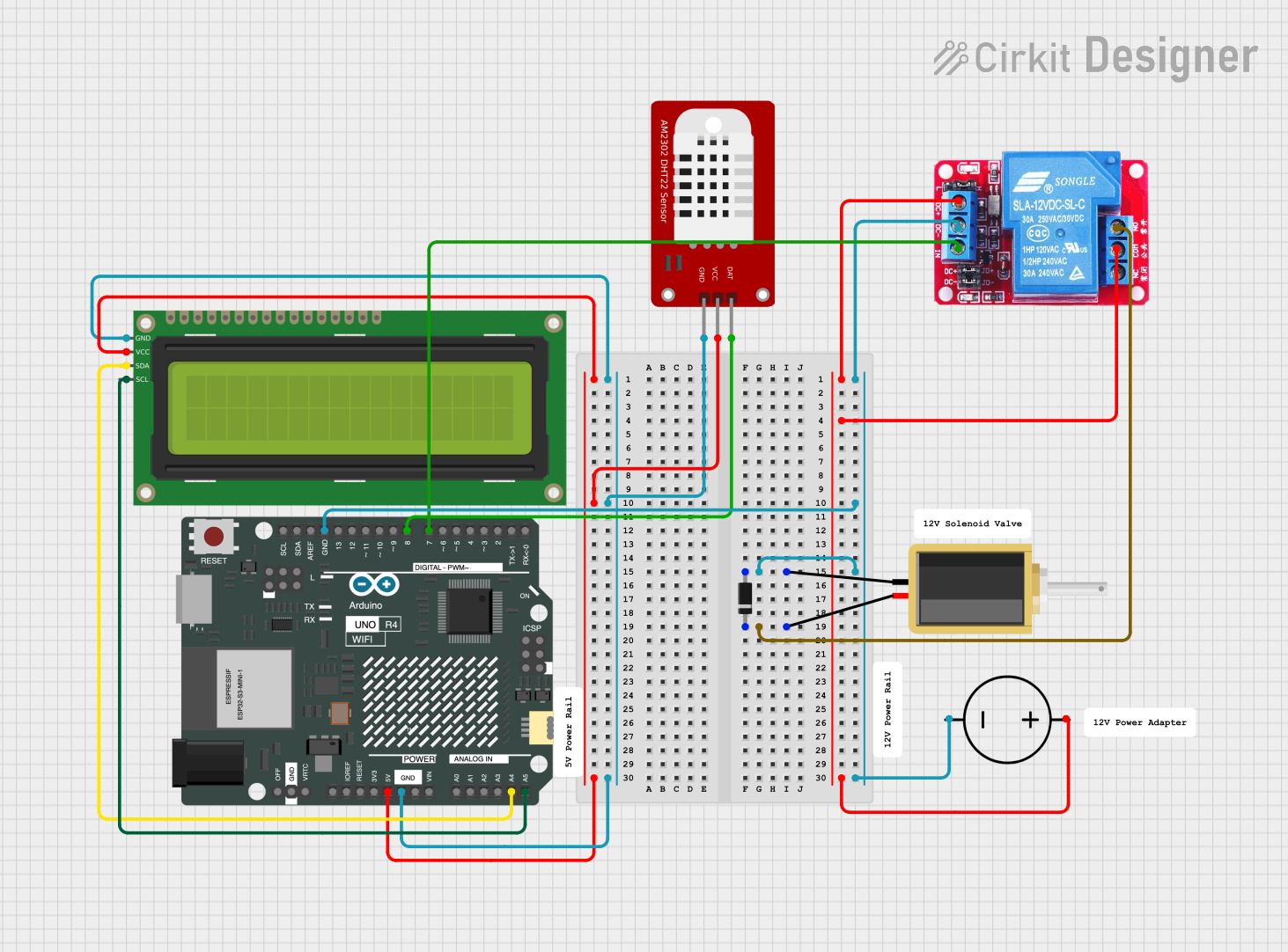
Circuit Documentation
Summary
This circuit involves an Arduino UNO R4 WiFi microcontroller, a 16x2 I2C LCD, a DHT22 temperature and humidity sensor, a 12V relay, a solenoid, a diode, and a DC power source. The Arduino UNO R4 WiFi serves as the central controller, interfacing with the LCD for display, the DHT22 for sensing temperature and humidity, and the relay for controlling the solenoid. The DC power source provides the necessary power for the components.
Component List
Diode
- Description: A diode used to ensure current flows in one direction.
- Pins: Cathode, Anode
Arduino UNO R4 WiFi
- Description: A microcontroller board based on the ATmega328P, with built-in WiFi capabilities.
- Pins: OFF, GND, VRTC, IIC0_SCL, IIC0_SDA, 3V3, GPIO 41, GPIO 0, GPIO 42, GPIO 43, GPIO 44, BOOT, IOREF, RESET, 5V, VIN, A0, A1, A2, A3, A4, A5, RSPCKA, CIPO, COPI, D0/RX, D1/TX, D2, D3, D4, D5, D6, D7, D8, D9, D10, D11, D12, D13, AREF, SDA, SCL
16x2 I2C LCD
- Description: A 16x2 character LCD display with I2C interface.
- Pins: GND, VCC, SDA, SCL
DHT22
- Description: A temperature and humidity sensor.
- Pins: GND, VCC, DAT
DC Power Source
- Description: A power source providing DC voltage.
- Pins: Ground, Positive
Solenoid
- Description: An electromechanical device that converts electrical energy into linear motion.
- Pins: Pin1, Pin2
12V Relay
- Description: A relay that operates on 12V to control high-power devices.
- Pins: NO, COM, NC, DC+, DC-, IN
Wiring Details
Diode
- Anode: Connected to Solenoid Pin1, 12V Relay DC-, Arduino UNO R4 WiFi GND, DC Power Source Ground
- Cathode: Connected to Solenoid Pin2, 12V Relay NO
Arduino UNO R4 WiFi
- GND: Connected to Diode Anode, Solenoid Pin1, 12V Relay DC-, DC Power Source Ground, 16x2 I2C LCD GND, DHT22 GND
- 5V: Connected to 16x2 I2C LCD VCC, DHT22 VCC
- A4: Connected to 16x2 I2C LCD SDA
- A5: Connected to 16x2 I2C LCD SCL
- D7: Connected to 12V Relay IN
- D8: Connected to DHT22 DAT
16x2 I2C LCD
- VCC: Connected to Arduino UNO R4 WiFi 5V
- GND: Connected to Arduino UNO R4 WiFi GND
- SDA: Connected to Arduino UNO R4 WiFi A4
- SCL: Connected to Arduino UNO R4 WiFi A5
DHT22
- VCC: Connected to Arduino UNO R4 WiFi 5V
- GND: Connected to Arduino UNO R4 WiFi GND
- DAT: Connected to Arduino UNO R4 WiFi D8
DC Power Source
- Ground: Connected to Diode Anode, Solenoid Pin1, 12V Relay DC-, Arduino UNO R4 WiFi GND
- Positive: Connected to 12V Relay DC+, 12V Relay COM
Solenoid
- Pin1: Connected to Diode Anode, 12V Relay DC-, Arduino UNO R4 WiFi GND, DC Power Source Ground
- Pin2: Connected to Diode Cathode, 12V Relay NO
12V Relay
- NO: Connected to Diode Cathode, Solenoid Pin2
- COM: Connected to DC Power Source Positive
- DC+: Connected to DC Power Source Positive
- DC-: Connected to Diode Anode, Solenoid Pin1, Arduino UNO R4 WiFi GND, DC Power Source Ground
- IN: Connected to Arduino UNO R4 WiFi D7
Documented Code
Arduino UNO R4 WiFi Code
void setup() {
  // put your setup code here, to run once:

}

void loop() {
  // put your main code here, to run repeatedly:

}
This code is a basic template for the Arduino UNO R4 WiFi. The setup() function is where you initialize your components, and the loop() function is where you place the main logic that runs repeatedly.