ESP-32 Controlled Relay Switching for AC Bulbs
Circuit Documentation
Summary
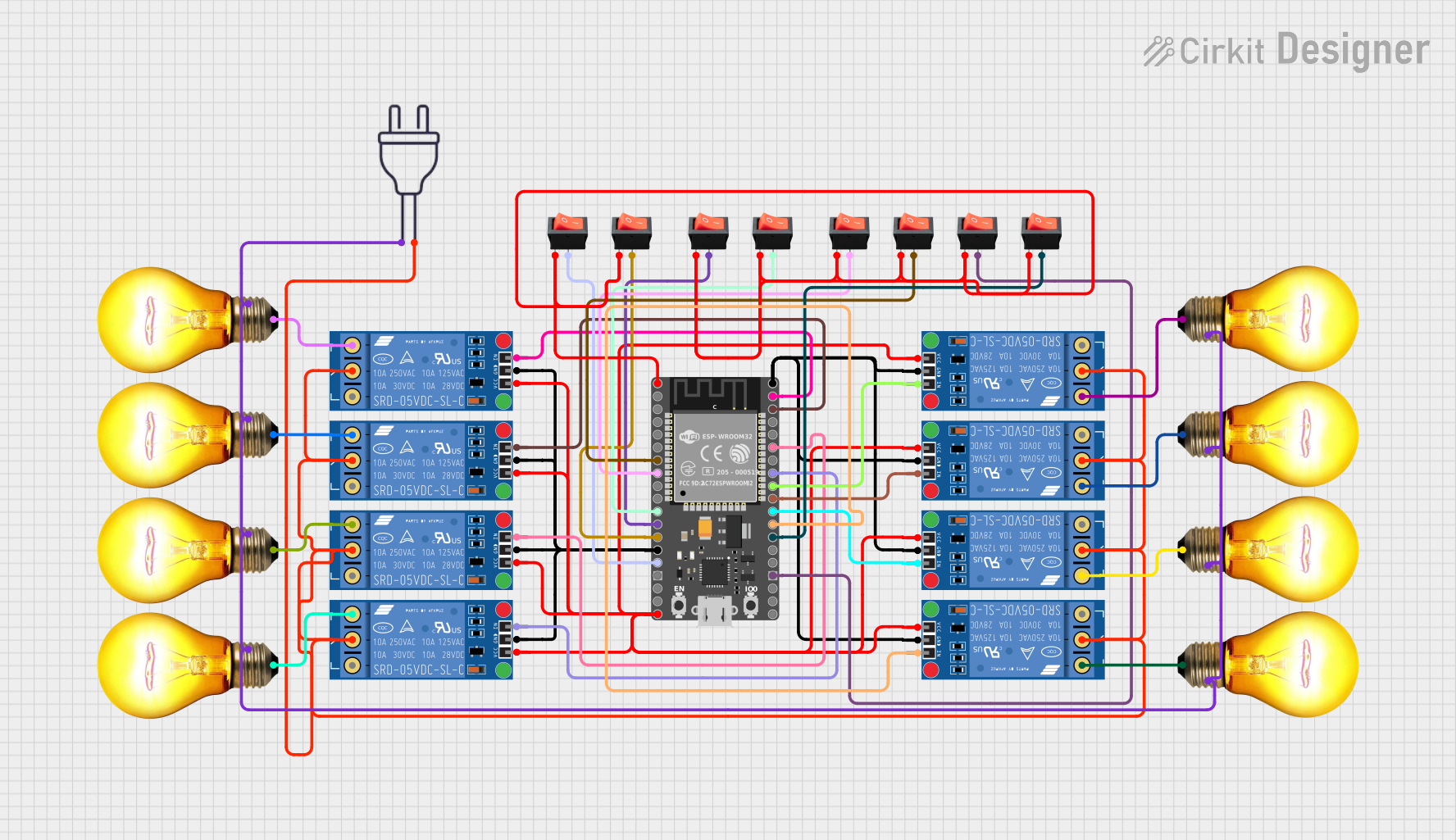
This circuit is designed to control multiple AC bulbs using KF-301 relays, which are in turn controlled by a HiLetgo ESP-32 microcontroller. The relays act as electrically operated switches that allow the microcontroller to handle high-power devices like AC bulbs. Rocker switches are used to provide manual control over the GPIO pins of the ESP-32, which likely serve as inputs to the microcontroller for various control logic.
Component List
- KF-301 Relay: An electromechanical switch that uses a low-power signal to control a higher power circuit. It has the following pins: signal, power, ground, Normally Closed (NC), Common (C), and Normally Open (NO).
- HiLetgo ESP-32: A microcontroller with Wi-Fi and Bluetooth capabilities. It has a variety of GPIO pins for interfacing with other electronic components.
- Rocker Switch: A simple on/off switch with two pins: output and input.
- AC Bulb: A standard bulb that operates on AC power. It has two pins: Phase (P) and Neutral (N).
- Power 220V: Represents the AC power source with two pins: hot wire and neutral wire.
Wiring Details
KF-301 Relay
- Signal: Connected to a GPIO pin on the ESP-32 for control.
- Power: Connected to the VIN pin on the ESP-32, shared among all relays.
- Ground: Connected to the GND pin on the ESP-32, shared among all relays.
- Common (C): Connected to the neutral wire of the 220V power source, shared among all relays.
- Normally Open (NO): Connected to the Phase (P) pin of an AC Bulb.
HiLetgo ESP-32
- 3.3V: Connected to the input pins of all rocker switches.
- GND: Shared ground with all KF-301 relays.
- VIN: Connected to the power pins of all KF-301 relays.
- GPIO: Various GPIO pins are connected to the signal pins of KF-301 relays and output pins of rocker switches.
Rocker Switch
- Input: Connected to the 3.3V pin on the ESP-32.
- Output: Connected to a GPIO pin on the ESP-32.
AC Bulb
- Phase (P): Connected to the Normally Open (NO) pin of a KF-301 relay.
- Neutral (N): Connected to the neutral wire of the 220V power source, shared among all bulbs.
Power 220V
- Hot Wire: Connected to the Phase (P) pin of an AC Bulb.
- Neutral Wire: Shared neutral connection with the Common (C) pin of all KF-301 relays and Neutral (N) pin of all AC Bulbs.
Documented Code
void setup() {
  // put your setup code here, to run once:

}

void loop() {
  // put your main code here, to run repeatedly:

}
The provided code is a template with empty setup() and loop() functions, which are standard in Arduino sketches. The setup() function is intended to contain initialization code that runs once when the microcontroller is powered on or reset. The loop() function is for code that runs continuously as long as the microcontroller is powered.
Additional code would be required to initialize the GPIO pins connected to the relays and to implement the control logic for turning the AC bulbs on and off based on the state of the rocker switches or other input conditions.