
Circuit Documentation
Summary of the Circuit
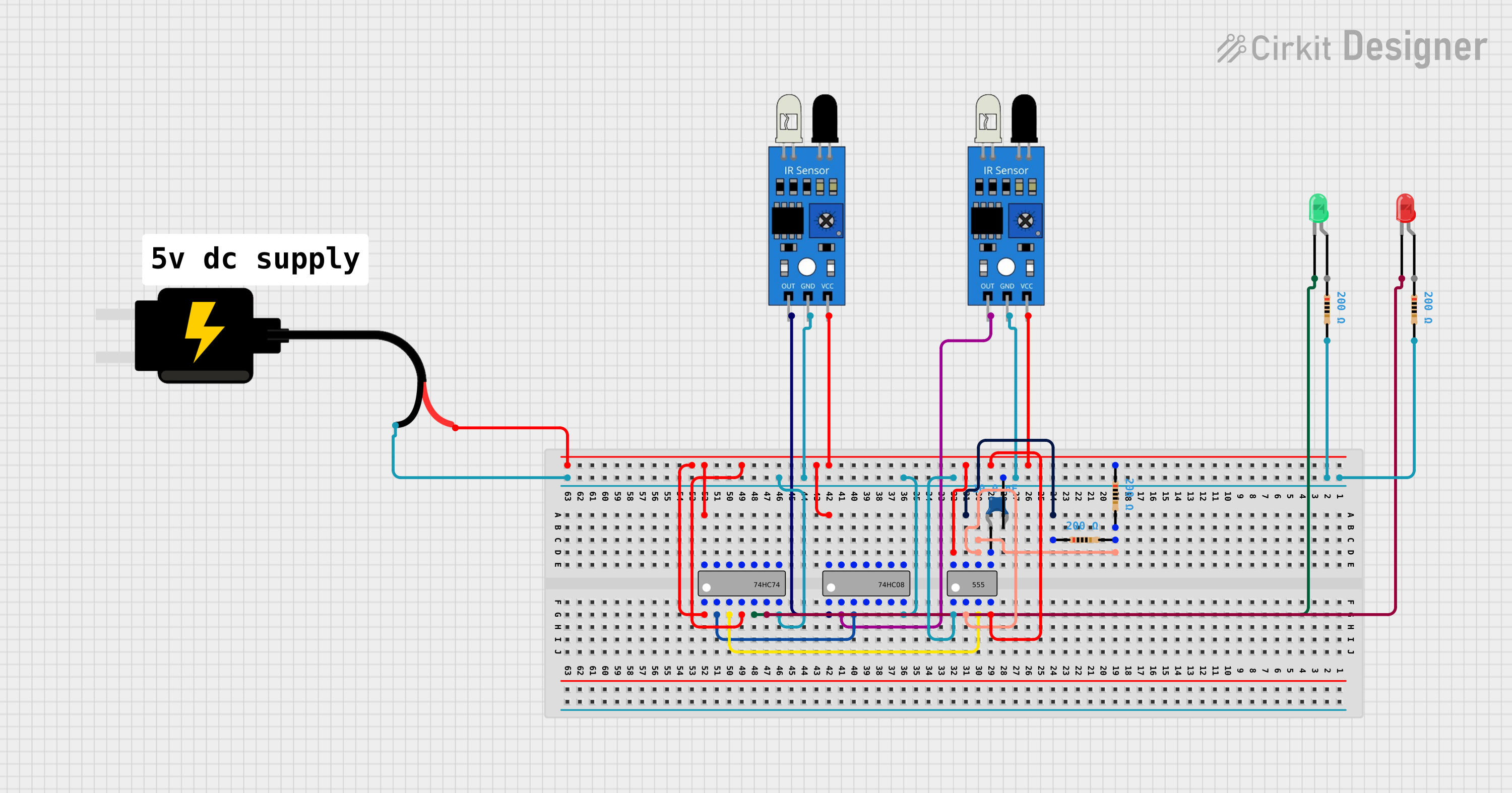
This circuit appears to be a combination of digital and analog components, including IR sensors, logic gates, a flip-flop, a timer IC (555), LEDs, resistors, and a capacitor. The circuit likely functions as a control or detection system, utilizing the IR sensors as inputs to the digital logic components, which then drive the LEDs based on the sensor outputs and timing signals from the 555 timer. The 555 timer is configured with external resistors and a capacitor, suggesting it may be set up in an astable or monostable mode for pulse generation. The logic gates and flip-flop are used to process the signals and control the state of the LEDs.
Component List
IR Sensor
- Pins: out, gnd, vcc
- Description: An infrared sensor used for detecting objects or motion.
74HC74 (Dual D-type Flip-Flop)
- Pins: Reset 1, Data 1, Clock 1, Set 1, Q1, ~Q1, GND, VCC, Reset 2, Data 2, Clock 2, Set 2, Q2, ~Q2
- Description: A dual D-type positive-edge-triggered flip-flop with individual data, set, reset, and clock inputs.
74HC08 (Quad 2-Input AND Gate)
- Pins: A1, B1, Y1, A2, B2, Y2, GND, VCC, B4, A4, Y4, B3, A3, Y3
- Description: A quad 2-input AND gate that provides the logic AND function.
555 Timer
- Pins: GND, TRIG, OUT, ~RESET, VCC, DIS, THR, CTRL
- Description: A versatile timer IC for generating accurate time delays or oscillation.
LED: Two Pin (Green)
- Pins: cathode, anode
- Description: A green light-emitting diode used as an indicator.
LED: Two Pin (Red)
- Pins: cathode, anode
- Description: A red light-emitting diode used as an indicator.
DC Source 5V
- Pins: VCC, GND
- Description: A 5V DC power source for the circuit.
Resistor
- Pins: pin1, pin2
- Description: A passive two-terminal electrical component that implements electrical resistance as a circuit element.
- Properties: Resistance value of 200 Ohms.
Ceramic Capacitor
- Pins: pin0, pin1
- Description: A fixed-value capacitor where the ceramic material acts as the dielectric.
- Properties: Capacitance value of 10 nF (1e-8 Farads).
Wiring Details
IR Sensor
- out: Connected to the input of the 74HC08 AND gate.
- gnd: Connected to the ground net of the circuit.
- vcc: Connected to the 5V power supply net.
74HC74 (Dual D-type Flip-Flop)
- Reset 1, Set 1, VCC: Connected to the 5V power supply net.
- Clock 1: Connected to the output of the 555 timer.
- Data 1: Connected to the output Y1 of the 74HC08 AND gate.
- Q1: Connected to the cathode of the green LED.
- ~Q1: Connected to the cathode of the red LED.
- GND: Connected to the ground net of the circuit.
74HC08 (Quad 2-Input AND Gate)
- A1, B1: Connected to the outputs of the IR sensors.
- Y1: Connected to the Data 1 input of the 74HC74 flip-flop.
- VCC: Connected to the 5V power supply net.
- GND: Connected to the ground net of the circuit.
555 Timer
- GND: Connected to the ground net of the circuit.
- TRIG, THR: Connected to each other and to the junction of two resistors.
- OUT: Connected to the Clock 1 input of the 74HC74 flip-flop.
- ~RESET: Connected to the 5V power supply net through a resistor.
- VCC: Connected to the 5V power supply net.
- DIS: Connected to one end of a resistor, the other end connected to the ground net.
- CTRL: Connected to one end of a ceramic capacitor, the other end connected to the ground net.
LED: Two Pin (Green)
- cathode: Connected to the Q1 output of the 74HC74 flip-flop.
- anode: Connected to the 5V power supply net through a resistor.
LED: Two Pin (Red)
- cathode: Connected to the ~Q1 output of the 74HC74 flip-flop.
- anode: Connected to the 5V power supply net through a resistor.
DC Source 5V
- VCC: Connected to the VCC net of the circuit.
- GND: Connected to the ground net of the circuit.
Resistor
- pin1, pin2: Used in various places in the circuit, including the connections to the LEDs, the 555 timer, and the reset line.
Ceramic Capacitor
- pin0, pin1: Connected between the CTRL pin of the 555 timer and the ground net.
Documented Code
No code has been provided for the microcontrollers in the circuit. If code is later provided, it should be documented here with explanations of how it interacts with the hardware components and implements the desired functionality.