
Arduino UNO and ESP8266-Based Smart Lock with Keypad and LCD Display
View and Edit Project In Cirkit Designer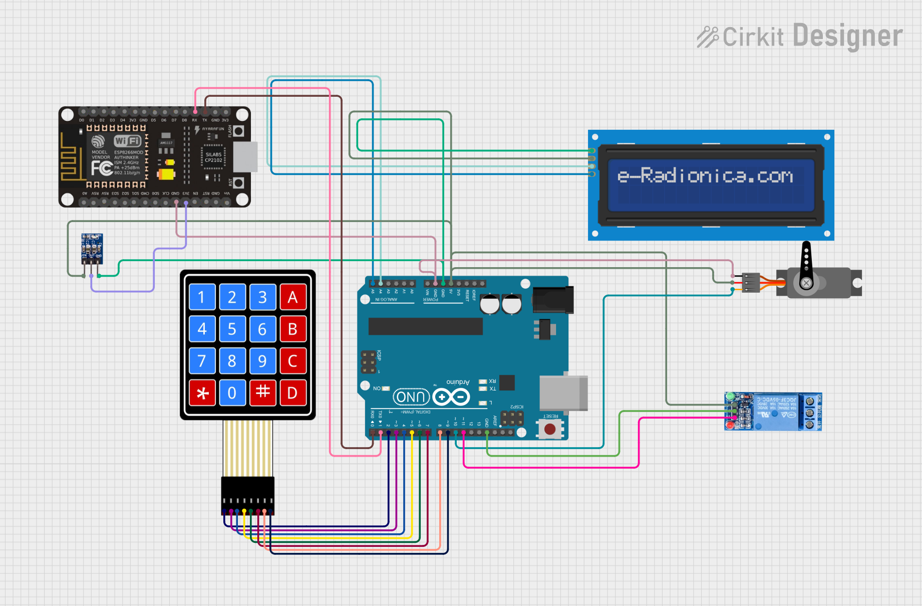
Circuit Documentation
Summary
This circuit is designed to interface a 4x4 membrane matrix keypad, an LCD screen, a servo motor, a relay, and an ESP8266 NodeMCU with an Arduino UNO. The keypad is used to input a PIN code, which is displayed on the LCD screen. If the correct PIN is entered, the servo motor moves, and the relay is activated. The ESP8266 NodeMCU is included for potential wireless communication capabilities.
Component List
4X4 Membrane Matrix Keypad
- Description: A keypad with 4 rows and 4 columns used for user input.
- Pins: R1, R2, R3, R4, C1, C2, C3, C4
Arduino UNO
- Description: A microcontroller board based on the ATmega328P.
- Pins: UNUSED, IOREF, Reset, 3.3V, 5V, GND, Vin, A0, A1, A2, A3, A4, A5, SCL, SDA, AREF, D13, D12, D11, D10, D9, D8, D7, D6, D5, D4, D3, D2, D1, D0
LCD screen 16x2 I2C
- Description: A 16x2 character LCD display with I2C interface.
- Pins: SCL, SDA, VCC, GND
Servo
- Description: A servo motor used for precise control of angular position.
- Pins: GND, VCC, PWM
1 Channel Relay 5V
- Description: A relay module used to control high voltage devices.
- Pins: VCC, GND, IN, NC, COM, NO
ESP8266 NodeMCU
- Description: A low-cost Wi-Fi microchip with full TCP/IP stack and microcontroller capability.
- Pins: D0, D1, D2, D3, D4, 3V3, GND, D5, D6, D7, D8, RX, TX, A0, RSV, SD3, SD2, SD1, CMD, SD0, CLK, EN, RST, VIN
AMS1117 3.3
- Description: A voltage regulator that outputs 3.3V.
- Pins: VIN, OUT, GND
Wiring Details
4X4 Membrane Matrix Keypad
- R1 connected to Arduino UNO D2
- R2 connected to Arduino UNO D3
- R3 connected to Arduino UNO D4
- R4 connected to Arduino UNO D5
- C1 connected to Arduino UNO D6
- C2 connected to Arduino UNO D7
- C3 connected to Arduino UNO D8
- C4 connected to Arduino UNO D9
Arduino UNO
- 5V connected to LCD screen 16x2 I2C VCC, Servo VCC, 1 Channel Relay 5V VCC, AMS1117 3.3 VIN
- GND connected to LCD screen 16x2 I2C GND, AMS1117 3.3 GND, 1 Channel Relay 5V GND, ESP8266 NodeMCU GND, Servo GND
- A4 connected to LCD screen 16x2 I2C SDA
- A5 connected to LCD screen 16x2 I2C SCL
- D11 connected to 1 Channel Relay 5V IN
- D10 connected to Servo PWM
- D1 connected to ESP8266 NodeMCU RX
- D0 connected to ESP8266 NodeMCU TX
LCD screen 16x2 I2C
- VCC connected to Arduino UNO 5V
- GND connected to Arduino UNO GND
- SDA connected to Arduino UNO A4
- SCL connected to Arduino UNO A5
Servo
- VCC connected to Arduino UNO 5V
- GND connected to Arduino UNO GND
- PWM connected to Arduino UNO D10
1 Channel Relay 5V
- VCC connected to Arduino UNO 5V
- GND connected to Arduino UNO GND
- IN connected to Arduino UNO D11
ESP8266 NodeMCU
- GND connected to Arduino UNO GND
- RX connected to Arduino UNO D1
- TX connected to Arduino UNO D0
- 3V3 connected to AMS1117 3.3 OUT
AMS1117 3.3
- VIN connected to Arduino UNO 5V
- OUT connected to ESP8266 NodeMCU 3V3
- GND connected to Arduino UNO GND
Code Documentation
#include <Keypad.h>
#include <Servo.h>
#include <Wire.h>
#include <LiquidCrystal_I2C.h>

// Define the servo motor
Servo myServo;

// Define the relay pin
const int relayPin = 12; // Adjust pin number as needed

// Define the keypad connections
const byte ROW_NUM    = 4; // Four rows
const byte COL_NUM    = 4; // Four columns

char keys[ROW_NUM][COL_NUM] = {
  {'1','2','3','A'},
  {'4','5','6','B'},
  {'7','8','9','C'},
  {'*','0','#','D'}
};

byte pin_rows[ROW_NUM] = {9, 8, 7, 6};    // Connect to the row pinouts of the keypad
byte pin_column[COL_NUM] = {5, 4, 3, 2}; // Connect to the column pinouts of the keypad

Keypad keypad = Keypad(makeKeymap(keys), pin_rows, pin_column, ROW_NUM, COL_NUM);

// Correct pin
String correctPin = "1234";  // Set the correct pin here
String enteredPin = "";  // Variable to store entered pin

// Initialize the LCD (16x2 with I2C address 0x27)
LiquidCrystal_I2C lcd(0x27, 16, 2);

void setup() {
  Serial.begin(9600);

  // Initialize the LCD with 16 columns and 2 rows
  lcd.begin(16, 2);  // Specify 16 columns and 2 rows
  lcd.backlight();   // Turn on the backlight
  lcd.clear();

  // Attach the servo to pin 10 (can be changed to any PWM-capable pin)
  myServo.attach(10);

  // Initialize the relay pin
  pinMode(relayPin, OUTPUT);
  digitalWrite(relayPin, LOW); // Relay off initially

  // Display message on LCD
  lcd.setCursor(0, 0);
  lcd.print("Enter Pin:");
}

void loop() {
  char key = keypad.getKey(); // Read the key pressed from the keypad

  if (key) { // If a key is pressed
    Serial.print("Key Pressed: ");
    Serial.println(key);

    if (key == '#') {
      // Check if entered pin matches correct pin
      if (enteredPin == correctPin) {
        lcd.clear();
        lcd.setCursor(0, 0);
        lcd.print("Correct Pin!");

        // Move the servo to 90 degrees
        myServo.write(90);
        delay(1000); // Wait for 1 second
        myServo.write(0);  // Move back to 0 degrees
        delay(1000); // Wait for 1 second

        // Turn on relay (can be used to control an external device)
        digitalWrite(relayPin, HIGH);
        delay(1000); // Keep the relay on for 1 second
        digitalWrite(relayPin, LOW); // Turn off relay
      } else {
        lcd.clear();
        lcd.setCursor(0, 0);
        lcd.print("Incorrect Pin");
      }
      enteredPin = ""; // Clear the entered pin after checking
    } else if (key == '*') {
      // Clear the entered pin if '*' is pressed
      enteredPin = "";
      lcd.clear();
      lcd.setCursor(0, 0);
      lcd.print("Pin Cleared.");
    } else {
      // Add the pressed key to the entered pin
      enteredPin += key;
    }

    // Display entered pin on LCD (Optional, for debugging purposes)
    lcd.setCursor(0, 1);
    lcd.print("Entered: ");
    lcd.print(enteredPin);
  }
}
This code initializes the components, sets up the keypad, LCD, servo, and relay, and continuously checks for key presses on the keypad. If the correct PIN is entered, the servo moves, and the relay is activated. The LCD displays the entered PIN and messages indicating whether the entered PIN is correct or incorrect.