Cirkit Designer
Your all-in-one circuit design IDE
Home /
Project Documentation
Arduino UNO Water Level Monitoring System with GSM Notification and LED Indicator
Circuit Documentation
Summary
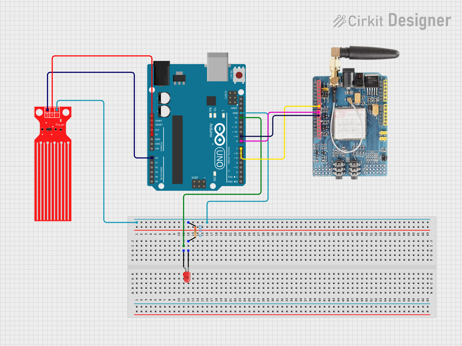
This circuit is designed to monitor water levels using a water level sensor and an Arduino UNO. The water level readings are displayed via serial communication, and an LED is used to indicate when the water level exceeds a certain threshold. Additionally, a GSM SIM900 module is included for potential communication purposes.
Component List
Water Level Sensor
- Description: Measures the water level and outputs an analog signal.
- Pins: SIG, VCC, GND
Arduino UNO
- Description: A microcontroller board based on the ATmega328P.
- Pins: UNUSED, IOREF, Reset, 3.3V, 5V, GND, Vin, A0, A1, A2, A3, A4, A5, SCL, SDA, AREF, D13, D12, D11, D10, D9, D8, D7, D6, D5, D4, D3, D2, D1, D0
Resistor
- Description: Limits the current flowing through the LED.
- Pins: pin1, pin2
- Properties:
- Resistance: 220 Ohms
LED: Two Pin (red)
- Description: A red LED used to indicate the water level status.
- Pins: cathode, anode
GSM SIM900
- Description: A GSM module used for communication purposes.
- Pins: A5, A4, A3, A2, A1, A0, 5V, GND, 3.3V, RESET, D0, D1, D2, D3, D4, D5, D6, D7, D8, D9, D10, D11, D12, D13, AREF
Wiring Details
Water Level Sensor
- SIG connected to Arduino UNO A0
- VCC connected to Arduino UNO 5V
- GND connected to Resistor pin1 and Arduino UNO GND
Arduino UNO
- A0 connected to Water Level Sensor SIG
- 5V connected to Water Level Sensor VCC
- GND connected to Resistor pin1 and Water Level Sensor GND
- D13 connected to LED anode
- D9 connected to GSM SIM900 D9
- D8 connected to GSM SIM900 D8
- D7 connected to GSM SIM900 D7
Resistor
- pin1 connected to Water Level Sensor GND and Arduino UNO GND
- pin2 connected to LED cathode
LED: Two Pin (red)
- anode connected to Arduino UNO D13
- cathode connected to Resistor pin2
GSM SIM900
- D9 connected to Arduino UNO D9
- D8 connected to Arduino UNO D8
- D7 connected to Arduino UNO D7
Documented Code
// Define the pins
int waterSensorPin = A0;  // Water level sensor connected to analog pin A0
int ledPin = 13;          // LED connected to digital pin 13

void setup() {
  // Initialize serial communication at 9600 bits per second
  Serial.begin(9600);
  // Initialize the LED pin as an output
  pinMode(ledPin, OUTPUT);
}

void loop() {
  // Read the input on analog pin 0
  int sensorValue = analogRead(waterSensorPin);

  // Print out the value you read
  Serial.print("Water Level: ");
  Serial.println(sensorValue);

  // Check if the water level is above a threshold
  if (sensorValue > 300) {  // Adjust the threshold as necessary
    digitalWrite(ledPin, HIGH);  // Turn the LED on
  } else {
    digitalWrite(ledPin, LOW);   // Turn the LED off
  }

  // Wait for a second before taking the next reading
  delay(1000);
}
This code initializes the water level sensor and LED, reads the water level, and turns the LED on or off based on the water level reading. The water level is also printed to the serial monitor for monitoring purposes.