
Arduino-Controlled Smart Irrigation System with Water Level and Soil Moisture Sensing
View and Edit Project In Cirkit Designer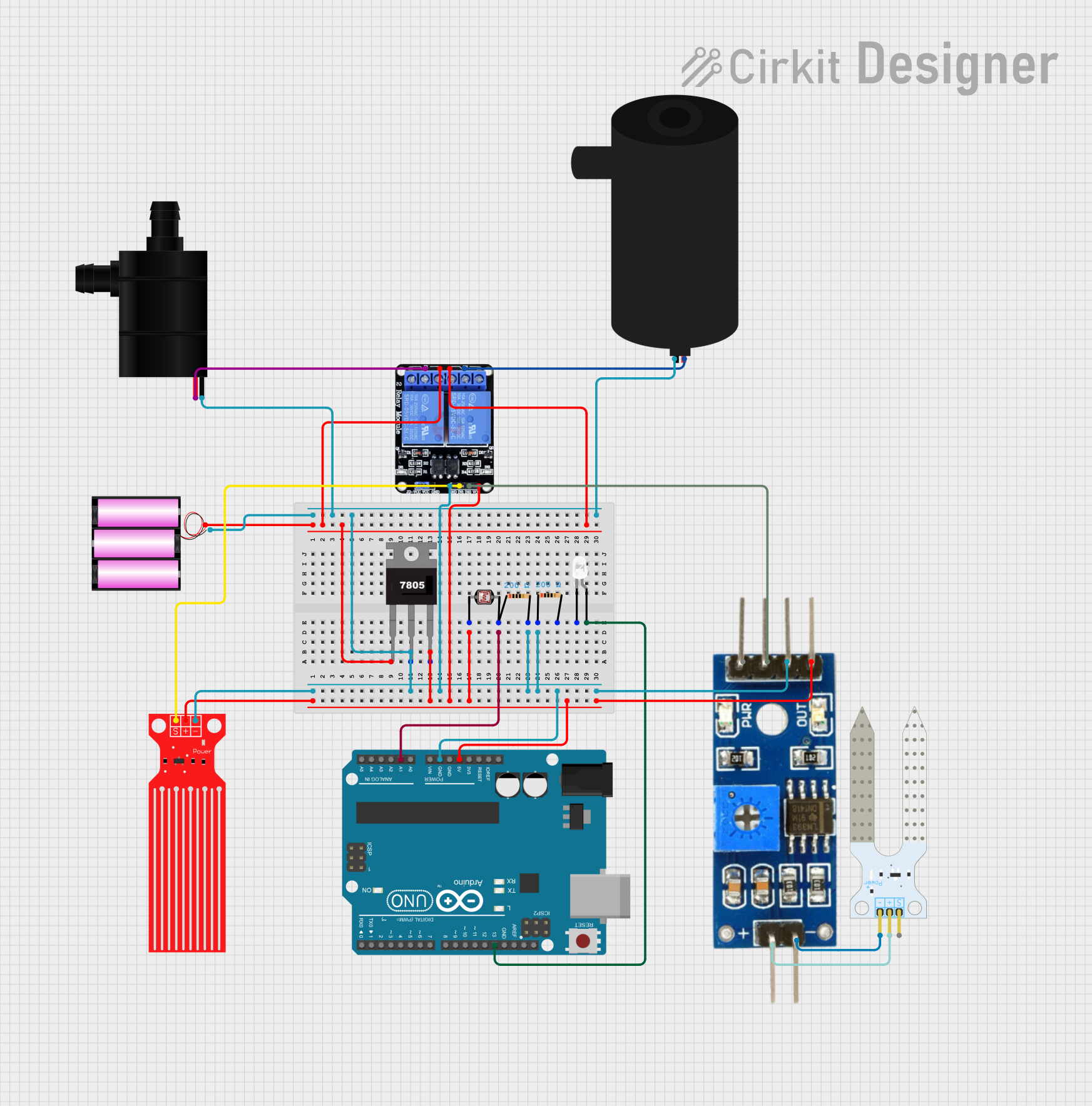
Circuit Documentation
Summary
This circuit is designed to control water pumps based on sensor inputs, with an Arduino UNO as the central microcontroller. It includes a voltage regulation system, a two-channel relay for controlling the pumps, and various sensors for detecting water levels and soil moisture. An LED is also included, likely for status indication.
Component List
- Battery 12V: Provides the main power source for the circuit.
- Two Channel Relay 5V: Allows for control of high-power devices with low-power signals from the microcontroller.
- Water Level Sensor: Detects the level of water in a container or environment.
- Water Pump: An electromechanical device used to move water through the system.
- 7805 Voltage Regulator: Regulates the input voltage down to a stable 5V output.
- Arduino UNO: The main microcontroller board that controls the circuit's logic.
- LED (White): An indicator light, typically used for signaling the circuit's status.
- Resistor (200 Ohms): Limits current, often used to protect components such as LEDs.
- Photocell (LDR): A light-dependent resistor used to detect light levels.
- Soil Moisture Module: Interfaces with a soil moisture sensor and provides digital and analog outputs.
- Soil Moisture Sensor: Measures the moisture content in the soil.
Wiring Details
Battery 12V
- Positive terminal connected to the input of the 7805 voltage regulator and the normally open (NO2) and normally closed (NC1) contacts of the Two Channel Relay.
- Negative terminal connected to the ground (GND) of various components including the Water Pump, water pump, 7805 voltage regulator, Two Channel Relay, Water Level Sensor, Arduino UNO, and both 200 Ohm Resistors.
Two Channel Relay 5V
- VCC connected to the 5V output of the 7805 voltage regulator.
- IN2 connected to the digital output of the Soil Moisture Module.
- IN1 connected to the signal output of the Water Level Sensor.
- GND connected to the system ground.
- NO2 and NC1 connected to the positive terminal of the Battery 12V.
- C2 connected to the positive terminal of the water pump.
- C1 connected to the VCC of the Water Pump.
Water Level Sensor
- SIG connected to IN1 of the Two Channel Relay.
- VCC connected to the 5V output of the 7805 voltage regulator.
- GND connected to the system ground.
Water Pump
- VCC connected to C1 of the Two Channel Relay.
- GND connected to the system ground.
7805 Voltage Regulator
- Vin connected to the positive terminal of the Battery 12V.
- Gnd connected to the system ground.
- Vout connected to the VCC of the Two Channel Relay, Water Level Sensor, Arduino UNO, and Soil Moisture Module.
Arduino UNO
- GND connected to the system ground.
- 5V connected to the 5V output of the 7805 voltage regulator.
- A1 connected to one end of a 200 Ohm Resistor, which is connected to the LDR.
- D13 connected to the anode of the LED.
LED (White)
- Anode connected to D13 of the Arduino UNO.
- Cathode connected to the system ground through a 200 Ohm Resistor.
Resistor (200 Ohms)
- One resistor connected between the anode of the LED and D13 of the Arduino UNO.
- Another resistor connected between A1 of the Arduino UNO and the LDR.
Photocell (LDR)
- One end connected to A1 of the Arduino UNO through a 200 Ohm Resistor.
- The other end connected to the 5V output of the 7805 voltage regulator.
Soil Moisture Module
- Positive connected to the VCC of the Soil Moisture Sensor.
- Negative connected to the GND of the Soil Moisture Sensor.
- Digital connected to IN2 of the Two Channel Relay.
- VCC connected to the 5V output of the 7805 voltage regulator.
- Ground connected to the system ground.
Soil Moisture Sensor
- VCC connected to the positive of the Soil Moisture Module.
- GND connected to the negative of the Soil Moisture Module.
- SIG not connected in the provided net list.
Documented Code
Arduino UNO Code (sketch.ino)
void setup() {
  // put your setup code here, to run once:

}

void loop() {
  // put your main code here, to run repeatedly:

}
The provided code is a template with empty setup() and loop() functions. The setup() function is intended for initialization code that runs once when the Arduino is powered on or reset. The loop() function contains the main logic that will run continuously.
Additional Notes
- The code for the Arduino UNO is currently a placeholder and needs to be completed with the logic for reading sensor data and controlling the relay and other outputs.
- The documentation file for the Arduino UNO code is empty and should be filled with relevant information about the code's functionality, usage, and any other important details.