
Arduino Mega 2560-Based Solenoid Control System with Hall Sensor and LED Indicator
View and Edit Project In Cirkit Designer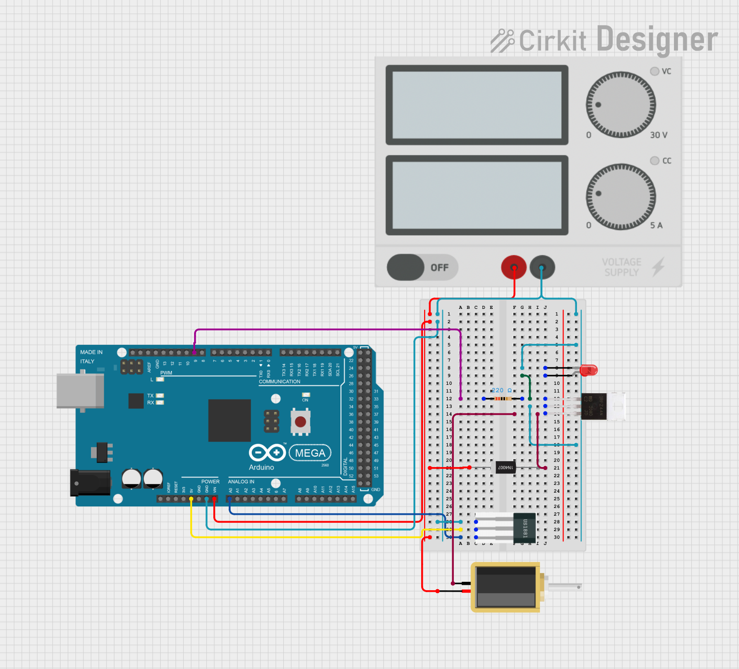
Circuit Documentation
Summary
This document provides a detailed overview of a circuit that includes an Arduino Mega 2560 microcontroller, a solenoid, a Hall sensor, an LED, a rectifier diode, a MOSFET, a resistor, and a power supply. The circuit is designed to control the solenoid based on the input from the Hall sensor, with visual feedback provided by the LED.
Component List
Arduino Mega 2560
- Description: A microcontroller board based on the ATmega2560.
- Pins: IOREF, RESET, 3V3, 5V, GND, VIN, A0-A15, D21/SCL, D20/SDA, D19/RX1, D18/TX1, D17 PWM/RX2, D16 PWM/TX2, D15/RX3, D14/TX3, D0 RX0, D1 TX0, D2-D13 PWM, AREF, SDA, SCL, D22-D53, 6swdw
Solenoid
- Description: An electromechanical device that converts electrical energy into mechanical motion.
- Pins: pin1, pin2
Hall Sensor
- Description: A sensor that detects the presence of a magnetic field.
- Pins: -, +, S
LED: Two Pin (red)
- Description: A red light-emitting diode.
- Pins: cathode, anode
1N4007 Rectifier Diode
- Description: A general-purpose rectifier diode.
- Pins: Cathode, Anode
IRFZ44N
- Description: A N-channel MOSFET.
- Pins: Gate, Drain, Source
Resistor
- Description: A 220 Ohm resistor.
- Pins: pin1, pin2
- Properties: Resistance: 220 Ohms
Power Supply
- Description: Provides power to the circuit.
- Pins: +, -
Wiring Details
Arduino Mega 2560
- 5V connected to + of Hall Sensor
- GND connected to - of Power Supply, - of Hall Sensor, cathode of LED, and Drain of IRFZ44N
- VIN connected to + of Power Supply, Cathode of 1N4007 Rectifier Diode, and pin2 of Solenoid
- A0 connected to S of Hall Sensor
- D9 PWM connected to pin1 of Resistor
Solenoid
- pin1 connected to Source of IRFZ44N
- pin2 connected to VIN of Arduino Mega 2560
Hall Sensor
- + connected to 5V of Arduino Mega 2560
- - connected to GND of Arduino Mega 2560
- S connected to A0 of Arduino Mega 2560
LED: Two Pin (red)
- cathode connected to GND of Arduino Mega 2560
- anode connected to pin2 of Resistor
1N4007 Rectifier Diode
- Cathode connected to VIN of Arduino Mega 2560
- Anode connected to pin2 of Solenoid
IRFZ44N
- Gate connected to pin2 of Resistor
- Drain connected to GND of Arduino Mega 2560
- Source connected to pin1 of Solenoid
Resistor
- pin1 connected to D9 PWM of Arduino Mega 2560
- pin2 connected to Gate of IRFZ44N and anode of LED
Power Supply
- + connected to VIN of Arduino Mega 2560
- - connected to GND of Arduino Mega 2560
Documented Code
Arduino Mega 2560 Code
void setup() {
  // put your setup code here, to run once:

}

void loop() {
  // put your main code here, to run repeatedly:

}
1N4007 Rectifier Diode Code
void setup() {
  // put your setup code here, to run once:

}

void loop() {
  // put your main code here, to run repeatedly:

}
This document provides a comprehensive overview of the circuit, including the components used, their wiring details, and the code for the microcontrollers.