
ESP8266 NodeMCU-Based Ultrasonic Distance Measurement with OV7725 Camera Feedback and Buzzer Alert System
View and Edit Project In Cirkit Designer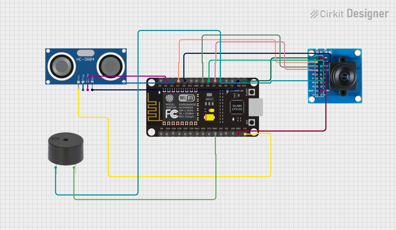
Circuit Documentation
Summary
This circuit integrates an ESP8266 NodeMCU microcontroller with an HC-SR04 Ultrasonic Sensor and an OV7725 camera module. Additionally, a buzzer is included in the design. The ESP8266 NodeMCU serves as the central processing unit, interfacing with the HC-SR04 sensor for distance measurement and the OV7725 camera module for image capture. The buzzer is likely used for audible feedback. The circuit is powered through the ESP8266 NodeMCU, which distributes power to the other components.
Component List
ESP8266 NodeMCU
- Description: A Wi-Fi enabled microcontroller module with GPIO pins.
- Pins: D0, D1, D2, D3, D4, 3V3, GND, D5, D6, D7, D8, RX, TX, A0, RSV, SD3, SD2, SD1, CMD, SD0, CLK, EN, RST, VIN
HC-SR04 Ultrasonic Sensor
- Description: An ultrasonic distance sensor module.
- Pins: VCC, TRIG, ECHO, GND
OV7725 Camera Module
- Description: A camera module capable of capturing images.
- Pins: 3V3, GND, SIOC, SIOD, VSYNC, HREF, PCLK, XCLK, D9, D8, D7, D6, D5, D4, D3, D2, RESET, D1, D0, PWDN
Buzzer
- Description: An electronic buzzer for audible alerts.
- Pins: PIN, GND
Wiring Details
ESP8266 NodeMCU
- D1 connected to HC-SR04 ECHO
- D2 connected to HC-SR04 TRIG
- D3 connected to OV7725 SIOC
- D4 connected to OV7725 SIOD
- D5 connected to OV7725 VSYNC
- D6 connected to OV7725 HREF
- D7 connected to OV7725 PCLK
- D8 connected to OV7725 XCLK and Buzzer PIN
- GND connected to HC-SR04 GND, Buzzer GND, and OV7725 GND
- 3V3 connected to OV7725 3V3
- VIN connected to HC-SR04 VCC
HC-SR04 Ultrasonic Sensor
- VCC connected to ESP8266 NodeMCU VIN
- TRIG connected to ESP8266 NodeMCU D2
- ECHO connected to ESP8266 NodeMCU D1
- GND connected to ESP8266 NodeMCU GND
OV7725 Camera Module
- 3V3 connected to ESP8266 NodeMCU 3V3
- GND connected to ESP8266 NodeMCU GND
- SIOC connected to ESP8266 NodeMCU D3
- SIOD connected to ESP8266 NodeMCU D4
- VSYNC connected to ESP8266 NodeMCU D5
- HREF connected to ESP8266 NodeMCU D6
- PCLK connected to ESP8266 NodeMCU D7
- XCLK connected to ESP8266 NodeMCU D8
- PWDN connected to GND (for normal operation)
Buzzer
- PIN connected to ESP8266 NodeMCU D8
- GND connected to ESP8266 NodeMCU GND
Documented Code
No code was provided for the microcontroller. The functionality of the circuit cannot be fully described without the embedded code that controls the ESP8266 NodeMCU and its interactions with the HC-SR04 Ultrasonic Sensor, the OV7725 camera module, and the buzzer. The code would typically initialize the peripherals, handle data acquisition from the sensor and camera, process the data, and provide output signals to the buzzer or other interfaces.