Arduino and Raspberry Pi Multi-Sensor Interface with Display and GPS Tracking
Circuit Documentation
Summary
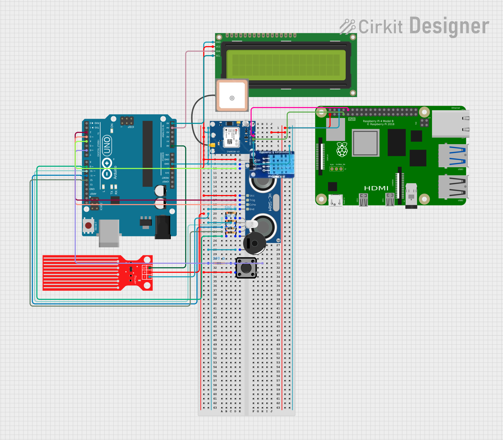
This circuit integrates a variety of components including an Arduino UNO, an HC-SR04 Ultrasonic Sensor, a 16x2 I2C LCD, a Raspberry Pi 4B, a Piezo Buzzer, a Water Level Sensor, an RGB LED, a GPS NEO 6M module, several resistors, a tactile switch, and a DHT11 temperature and humidity sensor. The Arduino UNO serves as the primary microcontroller, interfacing with sensors and output devices, while the Raspberry Pi 4B is used for more complex processing and communication with the GPS module. The circuit is designed to perform multiple functions, likely including distance measurement, environmental data collection, and user interaction through the switch and display.
Component List
Arduino UNO
A microcontroller board based on the ATmega328P. It has digital input/output pins, analog inputs, a USB connection for programming, and power management features.
HC-SR04 Ultrasonic Sensor
A sensor that measures distance by emitting ultrasonic waves and measuring the time taken for the echo to return.
16x2 I2C LCD
A liquid crystal display that can show 16 characters per line for 2 lines, with an I2C interface for communication.
Raspberry Pi 4B
A small single-board computer with a Broadcom processor, GPIO pins, USB ports, and various other interfaces.
Piezo Buzzer
An electronic device that emits sound when an electric signal is applied.
Water Level Sensor
A sensor that detects the level of water in a container or environment.
RGB LED (Wokwi compatible)
A light-emitting diode that can display multiple colors by mixing red, green, and blue light.
GPS NEO 6M
A module that provides location and timing information based on signals from GPS satellites.
Resistor (200 Ohms)
A passive two-terminal electrical component that implements electrical resistance as a circuit element.
Tactile Switch Buttons - 12mm Square
A simple switch mechanism for control of a device or process.
DHT11
A basic, ultra low-cost digital temperature and humidity sensor.
Wiring Details
Arduino UNO
5Vconnected to VCC of HC-SR04, 16x2 I2C LCD, Water Level Sensor, and one terminal of the tactile switch.GNDconnected to GND of HC-SR04, 16x2 I2C LCD, Water Level Sensor, Piezo Buzzer, RGB LED, and DHT11.D4connected to DATA of DHT11.D2connected to TRIG of HC-SR04.D3connected to ECHO of HC-SR04.D10connected to R of RGB LED through a 200 Ohm resistor.D11connected to G of RGB LED through a 200 Ohm resistor.D12connected to B of RGB LED through a 200 Ohm resistor.D9connected to pin 1 of Piezo Buzzer through a 200 Ohm resistor.A0connected to SIG of Water Level Sensor.A4(SDA) connected to SDA of 16x2 I2C LCD.A5(SCL) connected to SCL of 16x2 I2C LCD.
HC-SR04 Ultrasonic Sensor
VCCconnected to 5V of Arduino UNO.TRIGconnected to D2 of Arduino UNO.ECHOconnected to D3 of Arduino UNO.GNDconnected to GND of Arduino UNO.
16x2 I2C LCD
VCCconnected to 5V of Arduino UNO.GNDconnected to GND of Arduino UNO.SDAconnected to A4 (SDA) of Arduino UNO.SCLconnected to A5 (SCL) of Arduino UNO.
Raspberry Pi 4B
3V3connected to VCC of GPS NEO 6M.GNDconnected to GND of GPS NEO 6M.GPIO4connected to TX of GPS NEO 6M.GPIO15connected to RX of GPS NEO 6M.
Piezo Buzzer
pin 1connected to D9 of Arduino UNO through a 200 Ohm resistor.pin 2connected to GND of Arduino UNO.
Water Level Sensor
SIGconnected to A0 of Arduino UNO.VCCconnected to 5V of Arduino UNO.GNDconnected to GND of Arduino UNO.
RGB LED (Wokwi compatible)
Rconnected to D10 of Arduino UNO through a 200 Ohm resistor.Gconnected to D11 of Arduino UNO through a 200 Ohm resistor.Bconnected to D12 of Arduino UNO through a 200 Ohm resistor.COMconnected to GND of Arduino UNO.
GPS NEO 6M
VCCconnected to 3V3 of Raspberry Pi 4B.RXconnected to GPIO15 of Raspberry Pi 4B.TXconnected to GPIO4 of Raspberry Pi 4B.GNDconnected to GND of Raspberry Pi 4B.
Resistor (200 Ohms)
- Four resistors are used in the circuit, each with a resistance of 200 Ohms. They are connected in series with the RGB LED pins and the Piezo Buzzer to limit the current.
Tactile Switch Buttons - 12mm Square
- One terminal connected to 5V of Arduino UNO.
- The other terminal connected to a 200 Ohm resistor, which is then connected to GND.
DHT11
DATAconnected to D4 of Arduino UNO.GNDconnected to GND of Arduino UNO.VCCconnected to 5V of Arduino UNO.
Documented Code
Arduino UNO Code (sketch.ino)
void setup() {
  // put your setup code here, to run once:

}

void loop() {
  // put your main code here, to run repeatedly:

}
Note: The code provided for the Arduino UNO is a template with empty setup and loop functions. The actual functionality needs to be implemented based on the requirements of the circuit.