Arduino UNO Controlled Sound-Activated Relay for AC LED Bulb

Circuit Documentation
Summary
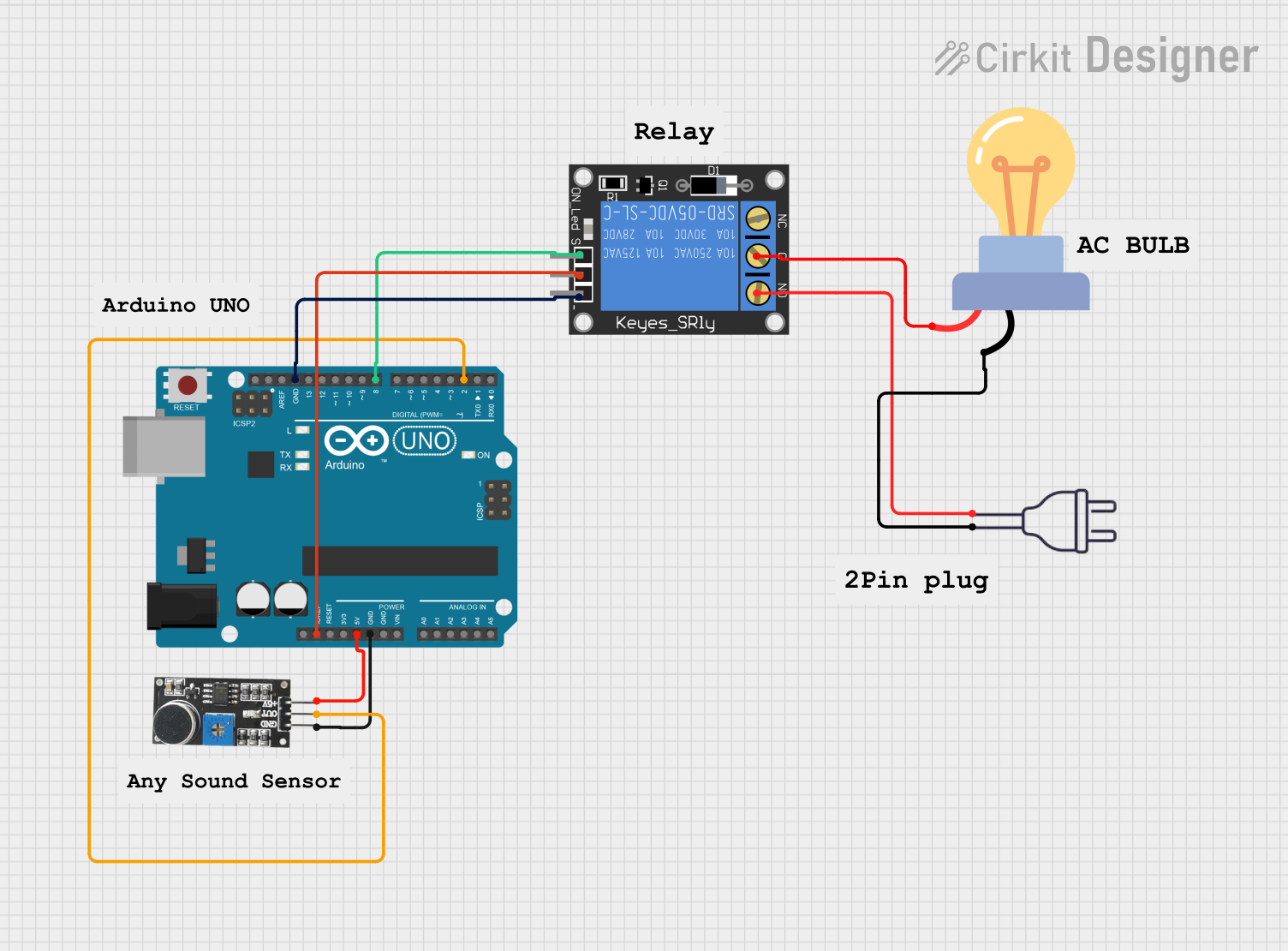
This circuit is designed to control an LED bulb using an Arduino UNO based on input from a sound sensor. The system uses a 1-channel relay to switch the LED bulb on and off in response to sound detected by the sound sensor. The Arduino UNO is programmed to read the sound sensor output and toggle the relay state accordingly, which in turn controls the power to the LED bulb connected to a 220V AC power source.
Component List
Arduino UNO
- Description: A microcontroller board based on the ATmega328P.
- Purpose: Acts as the central controller for the circuit, reading sensor inputs and controlling the relay.
Sound Sensor
- Description: A sensor that detects sound and provides a digital output.
- Purpose: Provides input to the Arduino to trigger the relay when sound is detected.
1-Channel Relay (5V 10A)
- Description: An electromechanical switch that can be controlled by a low-power signal from the Arduino.
- Purpose: Switches the LED bulb on and off in response to the Arduino's commands.
Power 220V
- Description: The main AC power source for the circuit.
- Purpose: Provides the necessary power to the LED bulb.
LED Bulb AC
- Description: An LED bulb designed to operate on AC power.
- Purpose: The load in the circuit, which is controlled by the relay.
Wiring Details
Arduino UNO
- IOREF: Connected to the relay's power input.
- 5V: Provides power to the sound sensor.
- GND: Common ground for the sound sensor and relay.
- D8: Sends control signals to the relay.
- D2: Receives the digital output from the sound sensor.
Sound Sensor
- 5V +: Receives power from the Arduino's 5V pin.
- OUT: Sends the digital output to the Arduino's D2 pin.
- GND: Connected to the Arduino's ground.
1-Channel Relay (5V 10A)
- Power: Receives power from the Arduino's IOREF pin.
- Ground: Connected to the Arduino's ground.
- Signal: Receives control signals from the Arduino's D8 pin.
- C (Common): Connected to the LED bulb's positive pin.
- NO (Normally Open): Connected to the 220V power source's hot wire.
Power 220V
- Hot Wire: Connected to the relay's normally open (NO) contact.
- Neutral Wire: Connected to the LED bulb's negative pin.
LED Bulb AC
- + (Positive): Connected to the relay's common (C) contact.
- - (Negative): Connected to the 220V power source's neutral wire.
Documented Code
// Definitions
const int relayPin = 8;        // Relay Pin
const int soundSensorPin = 2;  // Sound Sensor Pin
int relayState = LOW;          // Initial relay state (light off)
int sensorValue = 0;           // Variable to store the value from the sound sensor
unsigned long lastDebounceTime = 0; // Variable for debounce
unsigned long debounceDelay = 200;  // Debounce delay 200 ms

void setup() {
  pinMode(relayPin, OUTPUT);           // Set Relay as output
  pinMode(soundSensorPin, INPUT);      // Set Sound Sensor as input
  digitalWrite(relayPin, relayState);  // Start with the relay off (light off)
}

void loop() {
  // Read the value from the sound sensor
  sensorValue = digitalRead(soundSensorPin);

  // If sound is detected
  if (sensorValue == HIGH && (millis() - lastDebounceTime) > debounceDelay) {
    lastDebounceTime = millis(); // Reset debounce timer

    // Toggle relay status
    relayState = !relayState;
    digitalWrite(relayPin, relayState);
  }
}
The code is written for the Arduino UNO and is responsible for reading the digital output from the sound sensor. When sound is detected and a certain debounce period has passed, the state of the relay is toggled, which in turn switches the LED bulb on or off. The relay ensures that the high voltage required for the LED bulb is safely controlled by the low-voltage Arduino output.