Cirkit Designer
Your all-in-one circuit design IDE
Home /
Project Documentation
Arduino Mega 2560 Environmental Monitoring System with Relay Control and Data Logging
Circuit Documentation
Summary
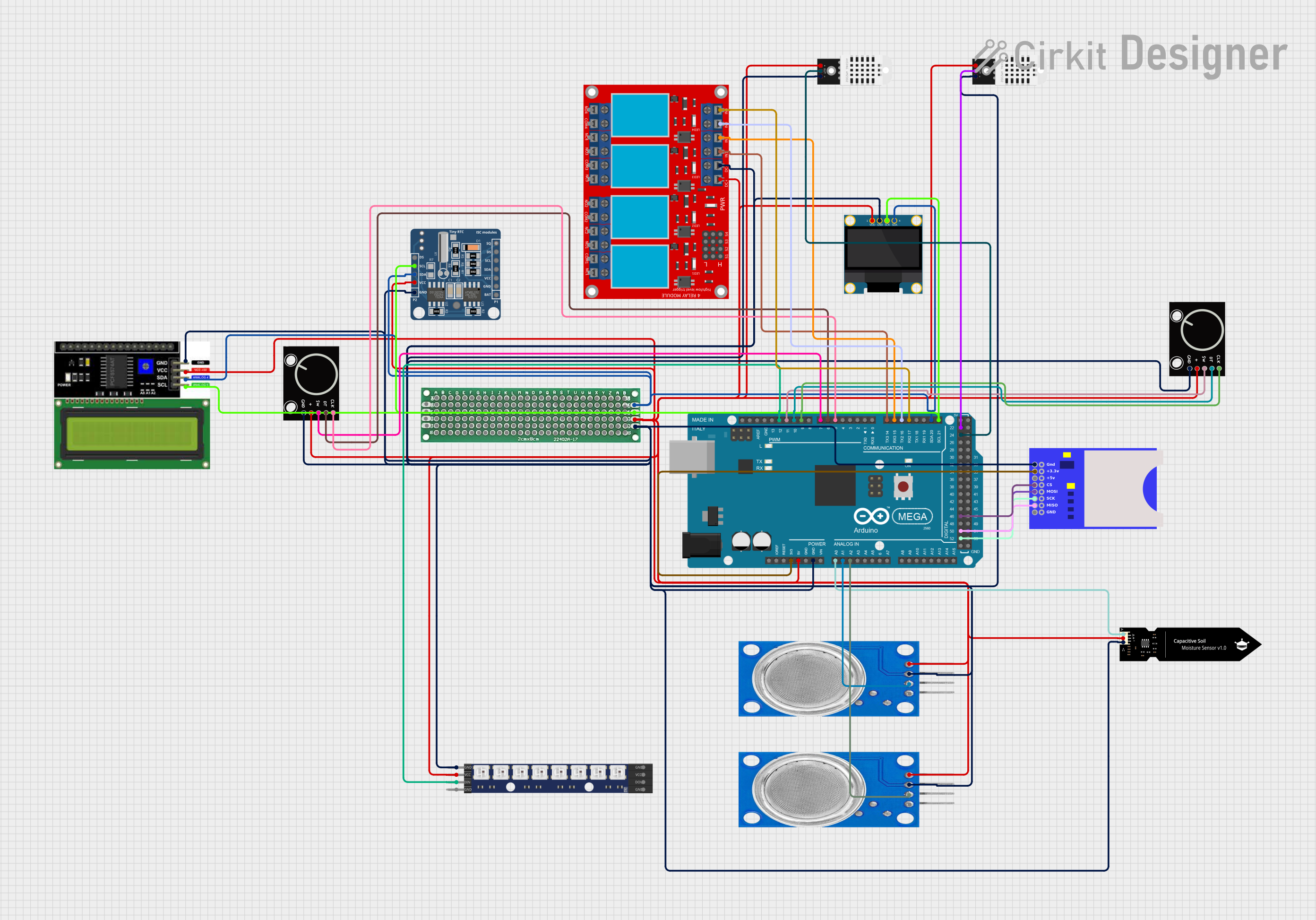
This circuit is designed to monitor environmental parameters such as temperature, humidity, CO2 levels, and soil moisture. It utilizes an Arduino Mega 2560 as the central microcontroller to read data from DHT22 sensors, MQ135 sensors, a capacitive soil moisture sensor, and to control a 4-channel relay module and an RGB LED matrix. The data is displayed on both an LCD and an OLED display. A rotary encoder allows the user to navigate through different data pages on the OLED display. The circuit also includes an RTC module for timekeeping and an SD card module for data logging.
Component List
Arduino Mega 2560
- Microcontroller board based on the ATmega2560
- Provides numerous digital and analog I/O pins
- Features I2C, SPI, and UART communication interfaces
4 Channel Relay Module
- Module with 4 electromechanical relays
- Each relay has normally open (N.O.), common (COM), and normally closed (N.C.) terminals
- Controlled by digital outputs from the Arduino
OLED 128x64 I2C Monochrome Display
- Small display for showing text and graphics
- Uses I2C communication protocol
- Typically used for displaying sensor data or menus
LCD I2C Display
- Alphanumeric liquid crystal display with I2C interface
- Displays time, date, and other status information
Rotary Encoder (x2)
- Input device that provides rotational position feedback
- Includes push-button functionality
- Used for navigating the OLED display interface
MQ135 Gas Sensor (x2)
- Air quality sensor for detecting a wide range of gases, including NH3, NOx, alcohol, benzene, smoke, and CO2
- Provides both analog and digital outputs
DFRobot Capacitive Soil Moisture Sensor (V1.0)
- Sensor for measuring the moisture content in soil
- Outputs an analog signal that varies with the moisture level
RTC DS1307
- Real-time clock module for timekeeping
- Uses I2C communication protocol
- Maintains time with a coin cell battery when power is lost
DHT22 Temperature and Humidity Sensor (x2)
- Digital sensor for measuring ambient temperature and humidity
- Provides calibrated digital output
WS2812 RGB LED Matrix 1x8
- Strip of 8 individually addressable RGB LEDs
- Controlled via a single digital pin
2cm x 8cm PCB
- Small prototyping printed circuit board
- Used for mounting and interconnecting components
SD Card Module
- Module for reading and writing to SD cards
- Uses SPI communication protocol
- Utilized for data logging purposes
Wiring Details
Arduino Mega 2560
3V3connected to SD card module+3.3V5Vconnected to various components' VCC pinsGNDconnected to various components' GND pinsA0toA2connected to analog pins of sensorsD21/SCLandD20/SDAconnected to I2C devices (LCD, OLED, RTC)D17 PWM/RX2toD14/TX3connected to relay module inputsIN 1toIN 4D5 PWMtoD11 PWMconnected to rotary encoder pinsCLK,DT,SWD12 PWMconnected to WS2812 RGB LED matrixDIND52,D50,D51,D46connected to SD card moduleSCK,MISO,MOSI,CSD24,D22connected to DHT22 sensorsOUTpins
4 Channel Relay Module
VCC+andVCC- (GND)connected to5VandGNDrespectivelyIN 1toIN 4controlled by Arduino pinsD14/TX3toD17 PWM/RX2
OLED 128x64 I2C Monochrome Display
VDDandGNDconnected to5VandGNDrespectivelySCKandSDAconnected to ArduinoD21/SCLandD20/SDA
LCD I2C Display
VCCandGNDconnected to5VandGNDrespectivelySDAandSCLconnected to ArduinoD20/SDAandD21/SCL
Rotary Encoder (x2)
+andGNDconnected to5VandGNDrespectivelySW,DT,CLKconnected to Arduino pinsD7 PWM,D6 PWM,D5 PWMfor one encoder andD11 PWM,D10 PWM,D9 PWMfor the other
MQ135 Gas Sensor (x2)
VCCandGNDconnected to5VandGNDrespectivelyA0connected to ArduinoA1andA2
DFRobot Capacitive Soil Moisture Sensor (V1.0)
VCCandGNDconnected to5VandGNDrespectivelyAconnected to ArduinoA0
RTC DS1307
VCCandGNDconnected to5VandGNDrespectivelySCLandSDAconnected to ArduinoD21/SCLandD20/SDA
DHT22 Temperature and Humidity Sensor (x2)
VCCandGNDconnected to5VandGNDrespectivelyOUTconnected to ArduinoD22andD24
WS2812 RGB LED Matrix 1x8
VCCandGNDconnected to5VandGNDrespectivelyDINconnected to ArduinoD12 PWM
SD Card Module
+3.3V,GND,+5Vconnected to Arduino3V3,GND,5VrespectivelyCS,MOSI,SCK,MISOconnected to ArduinoD46,D51,D52,D50
Documented Code
/*
 * This Arduino Sketch reads data from DHT22 sensors for temperature and
 * humidity, MQ135 sensors for CO2 levels, and a soil moisture sensor. It
 * displays the data on an LCD and OLED screen. The LCD shows the date and
 * time, while the OLED cycles through pages displaying temperature, humidity,
 * CO2 levels, and soil moisture. A rotary encoder is used to switch between
 * the pages on the OLED display. The code also controls a relay module and an
 * RGB LED matrix based on specific conditions.
 */

#include <Wire.h>
#include <LiquidCrystal_I2C.h>
#include <Adafruit_SSD1306.h>
#include <Adafruit_GFX.h>
#include <DHT.h>
#include <RTClib.h>
#include <Adafruit_NeoPixel.h>
#include <SD.h>

#define DHTPIN0 22
#define DHTPIN1 24
#define DHTTYPE DHT22
#define MQ135PIN0 A2
#define MQ135PIN1 A1
#define SOILMOISTUREPIN A0
#define OLED_RESET -1
#define SCREEN_WIDTH 128
#define SCREEN_HEIGHT 64
#define RELAY1 14
#define RELAY2 15
#define RGB_PIN 12
#define NUMPIXELS 8
#define SD_CS 46

DHT dht0(DHTPIN0, DHTTYPE);
DHT dht1(DHTPIN1, DHTTYPE);
LiquidCrystal_I2C lcd(0x27, 16, 2);
Adafruit_SSD1306 display(SCREEN_WIDTH, SCREEN_HEIGHT, &Wire, OLED_RESET);
RTC_DS1307 rtc;
Adafruit_NeoPixel pixels(NUMPIXELS, RGB_PIN, NEO_GRB + NEO_KHZ800);
File dataFile;

int page = 0;
const int totalPages = 4;
unsigned long previousMillis = 0;
const long interval = 20000;
bool relay2State = false;

void setup() {
  Wire.begin();
  lcd.begin();
  lcd.backlight();
  display.begin(SSD1306_SWITCHCAPVCC, 0x3C);
  display.display();
  delay(2000);
  display.clearDisplay();
  dht0.begin();
  dht1.begin();
  rtc.begin();
  pinMode(9, INPUT);
  pinMode(10, INPUT);
  pinMode(11, INPUT);
  pinMode(RELAY1, OUTPUT);
  pinMode(RELAY2, OUTPUT);
  pixels.begin();
  if (!SD.begin(SD_CS)) {
    lcd.print("SD init failed!");
    return;
  }
  dataFile = SD.open("datalog.txt", FILE_WRITE);
}

void loop() {
  DateTime now = rtc.now();
  lcd.setCursor(0, 0);
  lcd.print(now.year(), DEC);
  lcd.print('/');
  lcd.print(now.month(), DEC);
  lcd.print('/');