
Arduino UNO R4 WiFi-Controlled IR Sensor and Servo with I2C LCD Display Interface
View and Edit Project In Cirkit Designer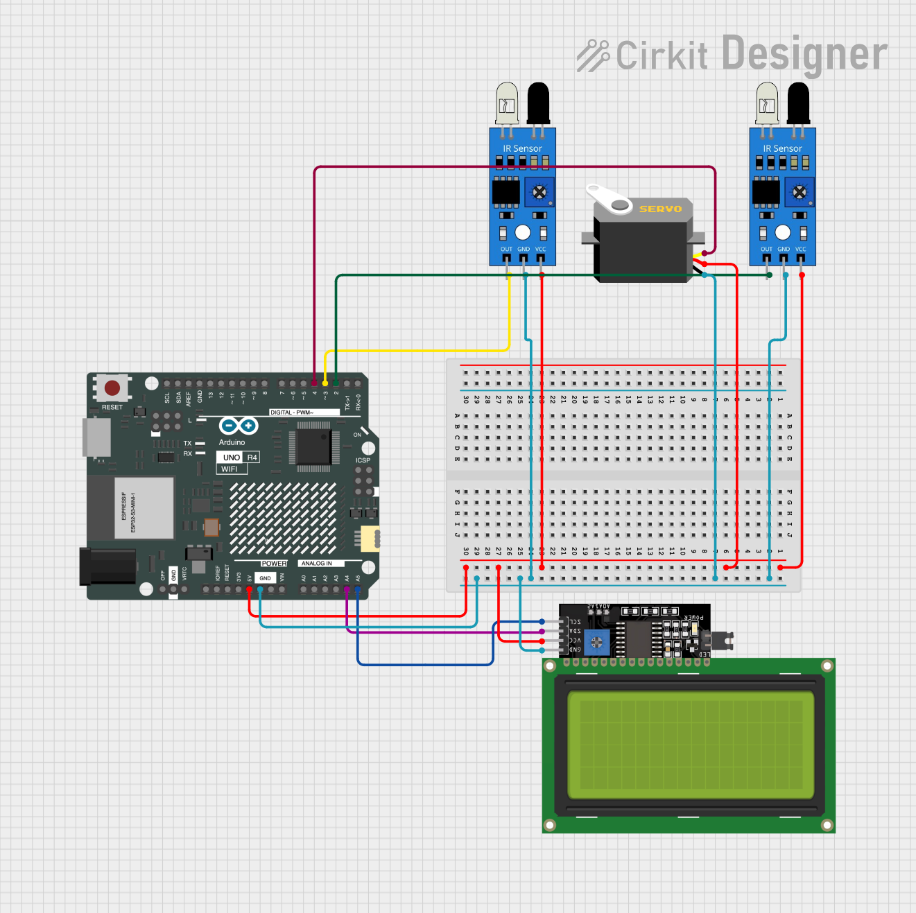
Circuit Documentation
Summary
The circuit in question is designed to interface an Arduino UNO R4 WiFi with an array of peripherals including two IR sensors, a servo motor, and an LCD Display (20x4 characters) with an I2C interface. The Arduino serves as the central processing unit, controlling the servo based on input from the IR sensors and displaying information on the LCD. The IR sensors detect the presence or absence of objects, the servo motor responds to the signals from the Arduino, and the LCD provides a user interface to display data.
Component List
IR Sensor
- Pins: out, gnd, vcc
- Description: An infrared sensor capable of detecting object presence.
Servo
- Pins: gnd, vcc, pulse
- Description: A motor that can be precisely controlled to move to a specified position.
LCD Display 20x4 I2C
- Pins: SCL, SDA, VCC, GND
- Description: A 20x4 character LCD display with an I2C interface for displaying text and numbers.
Arduino UNO R4 WiFi
- Pins: OFF, GND, VRTC, IIC0_SCL, IIC0_SDA, 3V3, GPIO 41, GPIO 0, GPIO 42, GPIO 43, GPIO 44, BOOT, IOREF, RESET, 5V, VIN, A0, A1, A2, A3, A4, A5, RSPCKA, CIPO, COPI, D0/RX, D1/TX, D2, D3, D4, D5, D6, D7, D8, D9, D10, D11, D12, D13, AREF, SDA, SCL
- Description: A microcontroller board based on the ATmega328, with integrated WiFi, used for controlling the various components in the circuit.
Wiring Details
IR Sensor 1
- VCC: Connected to 5V power supply from Arduino.
- GND: Connected to ground on Arduino.
- OUT: Connected to digital pin D2 on Arduino.
IR Sensor 2
- VCC: Connected to 5V power supply from Arduino.
- GND: Connected to ground on Arduino.
- OUT: Connected to digital pin D3 on Arduino.
Servo
- VCC: Connected to 5V power supply from Arduino.
- GND: Connected to ground on Arduino.
- PULSE: Connected to digital pin D4 on Arduino.
LCD Display 20x4 I2C
- VCC: Connected to 5V power supply from Arduino.
- GND: Connected to ground on Arduino.
- SDA: Connected to analog pin A4 on Arduino.
- SCL: Connected to analog pin A5 on Arduino.
Documented Code
Arduino UNO R4 WiFi
File: sketch.ino
void setup() {
  // put your setup code here, to run once:

}

void loop() {
  // put your main code here, to run repeatedly:

}
File: documentation.txt
(No additional documentation provided)
This concludes the documentation for the given circuit. The code provided is a template and does not contain any functional logic. It is expected that the user will implement the setup and loop functions to initialize the components and define the circuit's behavior during operation.