
Circuit Documentation
Summary of the Circuit
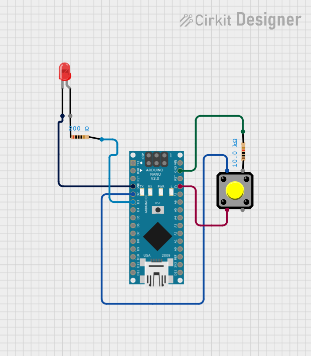
This circuit is designed to control an LED using a pushbutton. When the pushbutton is pressed, the LED lights up, and when the pushbutton is released, the LED turns off. The circuit utilizes an Arduino Nano as the microcontroller to read the state of the pushbutton and control the LED accordingly. The LED is connected through a resistor to limit the current, and there is also a pull-down resistor connected to the pushbutton to ensure a stable LOW signal when the button is not pressed.
Component List
Arduino Nano
- Description: A compact microcontroller board based on the ATmega328P.
- Pins: D1/TX, D0/RX, RESET, GND, D2, D3, D4, D5, D6, D7, D8, D9, D10, D11/MOSI, D12/MISO, VIN, 5V, A7, A6, A5, A4, A3, A2, A1, A0, AREF, 3V3, D13/SCK.
Pushbutton
- Description: A simple switch mechanism for controlling some aspect of a machine or a process.
- Pins: Pin 1, Pin 2, Pin 3, Pin 4.
Resistor (10k Ohms)
- Description: A passive two-terminal electrical component that implements electrical resistance as a circuit element.
- Resistance: 10,000 Ohms.
Resistor (200 Ohms)
- Description: Another resistor to limit the current flowing through the LED.
- Resistance: 200 Ohms.
LED: Two Pin (red)
- Description: A two-pin light-emitting diode that emits red light.
- Pins: Anode, Cathode.
Wiring Details
Arduino Nano
- GND connected to LED cathode.
- D2 connected to Pushbutton Pin 1.
- D3 connected to one end of the 200 Ohm Resistor.
- 5V connected to Pushbutton Pin 2.
- GND connected to one end of the 10k Ohm Resistor.
Pushbutton
- Pin 1 connected to Arduino Nano D2.
- Pin 2 connected to Arduino Nano 5V.
Resistor (10k Ohms)
- One end connected to Arduino Nano GND.
- The other end (not specified in the net list, assumed to be connected to Pushbutton Pin 1 for pull-down configuration).
Resistor (200 Ohms)
- One end connected to Arduino Nano D3.
- The other end (not specified in the net list, assumed to be connected to LED anode).
LED: Two Pin (red)
- Cathode connected to Arduino Nano GND.
- Anode (not specified in the net list, assumed to be connected to the other end of the 200 Ohm Resistor).
Documented Code
/*
 * This Arduino sketch controls an LED using a pushbutton.
 * When the pushbutton is pressed, the LED will light up.
 * When the pushbutton is released, the LED will turn off.
 */

const int buttonPin = 2; // Pin connected to the pushbutton
const int ledPin = 3;    // Pin connected to the LED through a resistor

void setup() {
  // Initialize the button pin as an input:
  pinMode(buttonPin, INPUT);
  // Initialize the LED pin as an output:
  pinMode(ledPin, OUTPUT);
}

void loop() {
  // Read the state of the pushbutton value:
  int buttonState = digitalRead(buttonPin);
  // Check if the pushbutton is pressed. If it is, the buttonState is HIGH:
  if (buttonState == HIGH) {
    // Turn LED on:
    digitalWrite(ledPin, HIGH);
  } else {
    // Turn LED off:
    digitalWrite(ledPin, LOW);
  }
}
This code is written for the Arduino Nano and is saved as a .ino file. It sets up the necessary input and output pins and contains a loop that continuously checks the state of the pushbutton. When the button is pressed, the LED is turned on; when it is released, the LED is turned off.