
Circuit Documentation
Summary of the Circuit
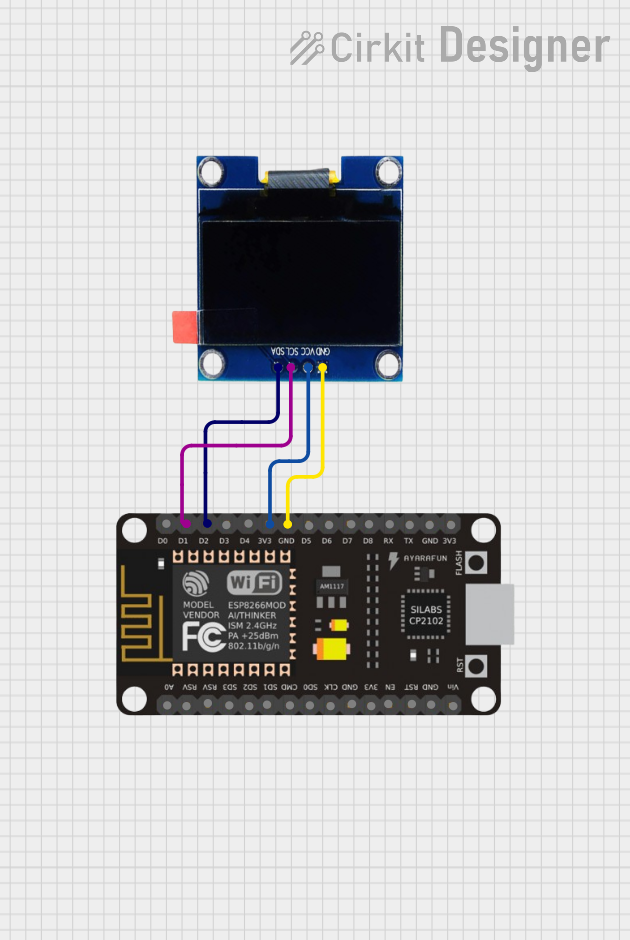
This circuit consists of an ESP8266 NodeMCU microcontroller board interfaced with a 1.3" OLED display. The ESP8266 NodeMCU provides the processing power and connectivity, while the OLED display serves as an output device to show information or data. The connection between the two components is established via the I2C communication protocol, utilizing two data lines: SCL (Serial Clock Line) and SDA (Serial Data Line). Additionally, the power supply lines are connected to provide the necessary voltage and ground reference.
Component List
ESP8266 NodeMCU
- Description: A Wi-Fi enabled microcontroller module with an ESP8266 chip.
- Pins: D0, D1, D2, D3, D4, 3V3, GND, D5, D6, D7, D8, RX, TX, A0, RSV, SD3, SD2, SD1, CMD, SD0, CLK, EN, RST, VIN
- Purpose: Acts as the main controller and communication interface for the circuit.
OLED 1.3"
- Description: A small 1.3-inch OLED display for visual output.
- Pins: GND, VCC, SCL, SDA
- Purpose: Displays information and data provided by the ESP8266 NodeMCU.
Wiring Details
ESP8266 NodeMCU
- D1 connected to OLED SCL
- D2 connected to OLED SDA
- 3V3 connected to OLED VCC
- GND connected to OLED GND
OLED 1.3"
- SCL connected to ESP8266 NodeMCU D1
- SDA connected to ESP8266 NodeMCU D2
- VCC connected to ESP8266 NodeMCU 3V3
- GND connected to ESP8266 NodeMCU GND
Documented Code
No code has been provided for the microcontroller. To fully utilize the circuit's capabilities, embedded code should be written and uploaded to the ESP8266 NodeMCU. The code should initialize and configure the I2C communication protocol, manage the Wi-Fi connectivity, and handle the display routines for the OLED screen.
When the code becomes available, it should be documented here with explanations for each function and routine, including setup and loop functions, I2C communication setup, Wi-Fi connection management, and OLED display control.