ESP32 CAM and NodeMCU V3 Controlled Robotic Vehicle with Servo Steering and L298N Motor Driver
Circuit Documentation
Summary
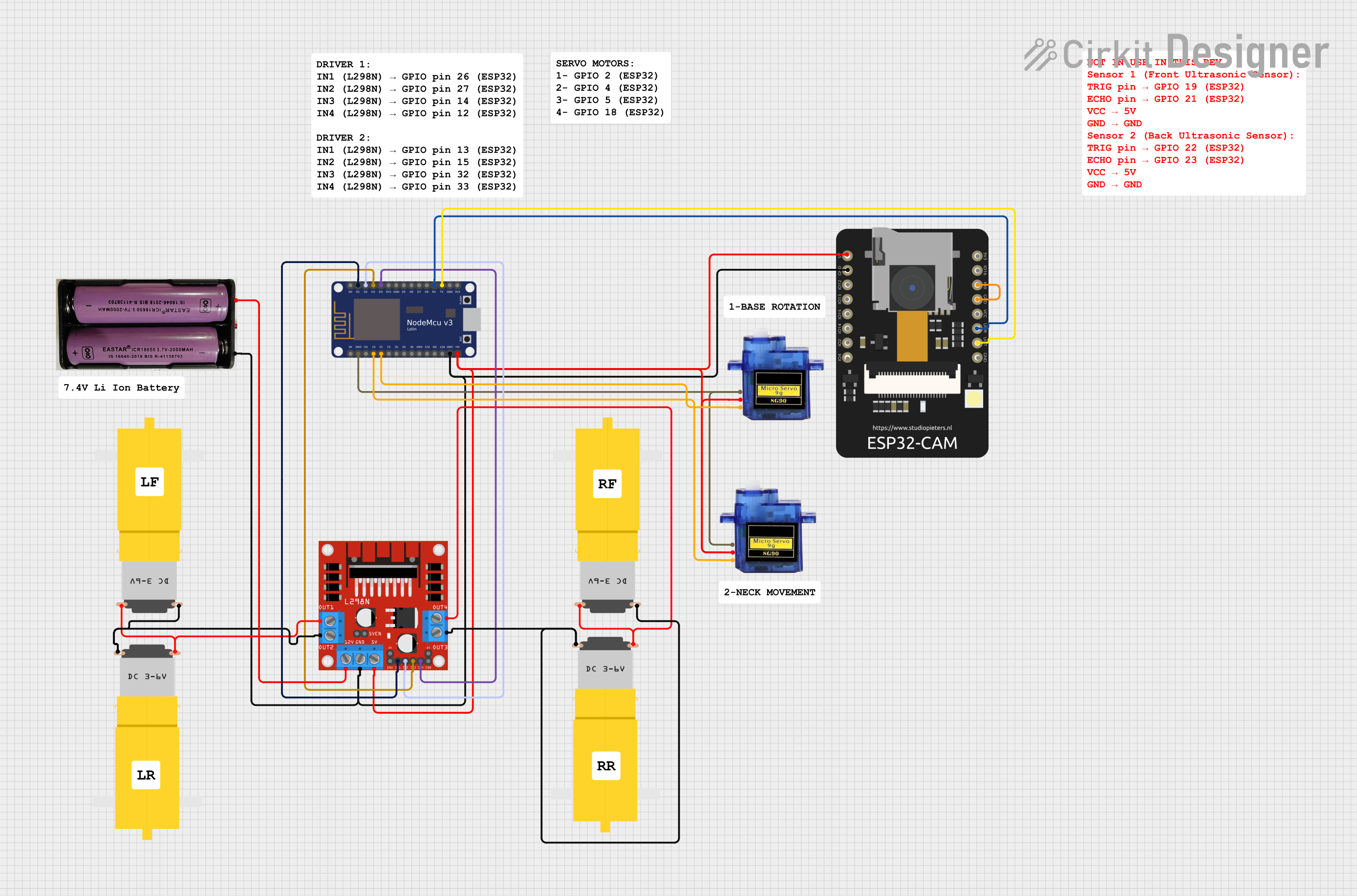
This circuit is designed to control a set of motors and servos using an ESP32 CAM and a NodeMCU V3 ESP8266 microcontroller. The circuit includes a motor driver (L298N DC motor driver) to manage the direction and speed of the motors. Power is supplied by a 7.4V battery, which is regulated for the microcontrollers and servos. Communication between the ESP32 CAM and the NodeMCU V3 ESP8266 is established via serial connection, allowing for potential image processing or Wi-Fi capabilities to be integrated into the control scheme.
Component List
Microcontrollers
- ESP32 CAM: A microcontroller with Wi-Fi and camera capabilities, used for image processing and/or wireless communication.
- NodeMCU V3 ESP8266: A microcontroller with integrated Wi-Fi, used for general control logic and interfacing with the motor driver and servos.
Power Supply
- 7.4V Battery: Provides the main power source for the motors and the motor driver, as well as the regulated power for the microcontrollers and servos.
Motor Driver
- L298N DC Motor Driver: Controls the direction and speed of up to four DC motors.
Motors
- Motor Amarillo Motorreductor Hobby: These are hobbyist DC motors that are controlled by the L298N motor driver.
Servos
- Micro Servo 9G: Small servos used for precise control of mechanical components.
Wiring Details
ESP32 CAM
- 5V: Connected to the 5V output from the L298N motor driver.
- GND: Common ground with the NodeMCU V3 ESP8266, L298N motor driver, and 7.4V battery.
- GPIO0: Connected to its own GND for enabling programming mode.
- GPIO3 / RX: Connected to the TX pin of the NodeMCU V3 ESP8266 for serial communication.
- GPIO1 / TX: Connected to the RX pin of the NodeMCU V3 ESP8266 for serial communication.
NodeMCU V3 ESP8266
- Vin: Connected to the 5V output from the L298N motor driver.
- GND: Common ground with the ESP32 CAM, L298N motor driver, and 7.4V battery.
- D1-D4: Connected to IN1-IN4 of the L298N motor driver for motor control signals.
- RX: Connected to the GPIO1 / TX of the ESP32 CAM.
- TX: Connected to the GPIO3 / RX of the ESP32 CAM.
- S2, S3: Connected to the PWM pins of the Micro Servo 9G for servo control.
L298N DC Motor Driver
- 12V: Connected to the + terminal of the 7.4V battery.
- GND: Common ground with the NodeMCU V3 ESP8266, ESP32 CAM, and 7.4V battery.
- 5V: Provides a regulated 5V output to the NodeMCU V3 ESP8266, ESP32 CAM, and Micro Servo 9G.
- OUT1, OUT2, OUT3, OUT4: Connected to the vcc and GND pins of the Motor Amarillo Motorreductor Hobby motors for driving the motors.
- IN1-IN4: Receive control signals from the D1-D4 pins of the NodeMCU V3 ESP8266.
Motor Amarillo Motorreductor Hobby
- vcc: Connected to OUT1 and OUT3 of the L298N motor driver.
- GND: Connected to OUT2 and OUT4 of the L298N motor driver.
Micro Servo 9G
- +5V: Connected to the 5V output from the L298N motor driver.
- GND: Common ground with the NodeMCU V3 ESP8266.
- PWM: Connected to the S2 and S3 pins of the NodeMCU V3 ESP8266 for control signals.
7.4V Battery
- +: Connected to the 12V input of the L298N motor driver.
- -: Common ground with the NodeMCU V3 ESP8266, ESP32 CAM, and L298N motor driver.
Documented Code
No code has been provided for the microcontrollers. The documentation of the code would typically include descriptions of the functions, the main control loop, and any libraries used for interfacing with the hardware components. Since no code is available, this section cannot be completed. If code becomes available, it should be documented here with appropriate explanations for each functional block and the overall logic flow.