
Arduino and ESP32-CAM Based Autonomous Robot with Ultrasonic Obstacle Detection and Battery Power
View and Edit Project In Cirkit Designer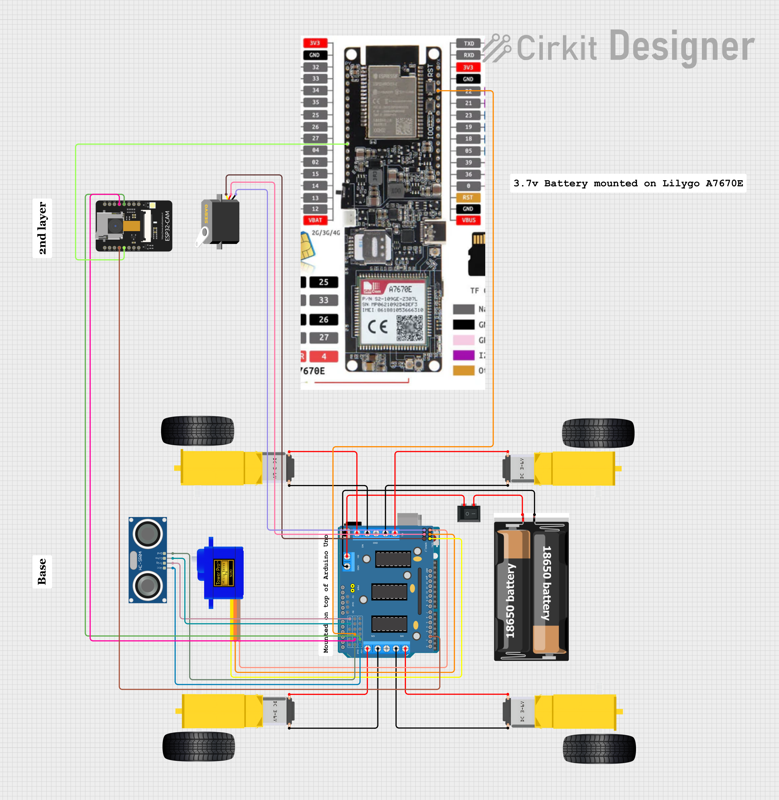
Circuit Documentation
Summary
This document provides a detailed overview of a circuit designed to control a robotic vehicle. The circuit includes various sensors, motors, and microcontrollers to enable autonomous navigation and obstacle avoidance. The primary components include an HC-SR04 Ultrasonic Sensor, multiple DC Gearmotors, a Servomotor, an ESP32-CAM, an Arduino UNO, and a DRIVER SHIELD L293D. The circuit is powered by a 2x 18650 battery pack and controlled via an Arduino UNO microcontroller.
Component List
HC-SR04 Ultrasonic Sensor
- Pins: VCC, TRIG, ECHO, GND
- Description: Ultrasonic distance sensor used for obstacle detection.
- Purpose: Measures distance to obstacles in front of the robot.
Gearmotor DC Wheels Left
- Pins: PIN1, PIN2
- Description: DC motor for driving the left wheels.
- Purpose: Provides movement to the left side of the robot.
Gearmotor DC Wheels Right
- Pins: PIN1, PIN2
- Description: DC motor for driving the right wheels.
- Purpose: Provides movement to the right side of the robot.
Servomotor SG90
- Pins: SIG, VCC, GND
- Description: Small servomotor for precise control.
- Purpose: Used for steering or other precise movements.
Rocker Switch (SPST)
- Pins: 1, 2
- Description: Single-pole single-throw switch.
- Purpose: Used to turn the circuit on and off.
ESP32-CAM
- Pins: 5V, GND, IO12, IO13, IO15, IO14, IO2, IO4, VOT, VOR, VCC, IO0, IO16, 3V3
- Description: Microcontroller with camera module.
- Purpose: Provides vision capabilities to the robot.
Arduino UNO
- Pins: UNUSED, IOREF, Reset, 3.3V, 5V, GND, Vin, A0, A1, A2, A3, A4, A5, SCL, SDA, AREF, D13, D12, D11, D10, D9, D8, D7, D6, D5, D4, D3, D2, D1, D0
- Description: Microcontroller board based on the ATmega328P.
- Purpose: Main controller for the robot.
2x 18650 Battery Pack
- Pins: vcc, gnd
- Description: Battery pack with two 18650 cells.
- Purpose: Provides power to the circuit.
DRIVER SHIELD L293D
- Pins: RESET, 3.3V, 5V, GND, VIN, 9V, A0, A1, A2, A3, A4, A5, M2 (+), M2 GND (-), M1 (+), M1 GND (-), M3 (+), M3 GND (-), M4 GND (-), M4 (+), SERVO_2, SERVO_1, RX/D0, TX/D1, D2, D3, D4, D5, D6, D7, D8, D9, D10, D11, ARef, D13, D12, VCC (External Power Supply), GND (External Power Supply)
- Description: Motor driver shield for Arduino.
- Purpose: Controls the motors and provides power distribution.
Lilygo 7670e
- Pins: 3v3, Gnd, Pin 32, pin 33, pin 34, pin35, pin 25, Pin 26, Pin 27, Pin 4, Pin 2, Pin 15, pin 14, Pin 13, Pin 12, VBAT, TXD, RXD, 3v3, Pin 22, Pin 21, Pin 23, Pin 19, Pin 18, Pin 5, Pin 39, Pin 36, Pin 0, RST, VBUS, LTE antenna, Gps Antenna, Type C
- Description: Microcontroller with various I/O pins.
- Purpose: Additional processing and control capabilities.
Wiring Details
HC-SR04 Ultrasonic Sensor
- VCC connected to DRIVER SHIELD L293D pin 5V
- TRIG connected to DRIVER SHIELD L293D pin A0
- ECHO connected to DRIVER SHIELD L293D pin A1
- GND connected to DRIVER SHIELD L293D pin GND
Gearmotor DC Wheels Left (Instance 1)
- PIN1 connected to DRIVER SHIELD L293D pin M4 (+)
- PIN2 connected to DRIVER SHIELD L293D pin M4 GND (-)
Gearmotor DC Wheels Left (Instance 2)
- PIN1 connected to DRIVER SHIELD L293D pin M2 GND (-)
- PIN2 connected to DRIVER SHIELD L293D pin M2 (+)
Gearmotor DC Wheels Right (Instance 1)
- PIN1 connected to DRIVER SHIELD L293D pin M3 GND (-)
- PIN2 connected to DRIVER SHIELD L293D pin M3 (+)
Gearmotor DC Wheels Right (Instance 2)
- PIN1 connected to DRIVER SHIELD L293D pin M1 (+)
- PIN2 connected to DRIVER SHIELD L293D pin M1 GND (-)
Servomotor SG90
- SIG connected to DRIVER SHIELD L293D pin SERVO_1
- VCC connected to DRIVER SHIELD L293D pin 5V
- GND connected to DRIVER SHIELD L293D pin GND
Rocker Switch (SPST)
- Pin 1 connected to DRIVER SHIELD L293D pin VCC (External Power Supply)
- Pin 2 connected to 2x 18650 pin vcc
2x 18650 Battery Pack
- vcc connected to Rocker Switch (SPST) pin 2
- gnd connected to DRIVER SHIELD L293D pin GND (External Power Supply)
ESP32-CAM
- GND connected to DRIVER SHIELD L293D pin GND
- VCC connected to DRIVER SHIELD L293D pin 5V
- IO13 connected to DRIVER SHIELD L293D pin D2
- IO15 connected to Lilygo 7670e pin Pin 2
Lilygo 7670e
- Gnd connected to DRIVER SHIELD L293D pin GND
Servo
- gnd connected to DRIVER SHIELD L293D pin GND
- vcc connected to DRIVER SHIELD L293D pin 5V
- pulse connected to DRIVER SHIELD L293D pin SERVO_2
Documented Code
#include <Servo.h>

volatile int IN1 = 11;
volatile int IN2 = 6;
volatile int IN3 = 5;
volatile int IN4 = 3;
volatile int rightDistance;
volatile int leftDistance;
Servo servo_4;

void left_side_forward(int speed) {
  analogWrite(IN1, speed * 0.92);
  analogWrite(IN2, 0);
}

void right_side_forward(int speed) {
  analogWrite(IN3, speed);
  analogWrite(IN4, 0);
}

void left_side_backward(int speed) {
  analogWrite(IN1, 0);
  analogWrite(IN2, speed * 0.92);
}

void right_side_backward(int speed) {
  analogWrite(IN3, 0);
  analogWrite(IN4, speed);
}

float checkdistance_A1_A2() {
  digitalWrite(A1, LOW);
  delayMicroseconds(2);
  digitalWrite(A1, HIGH);
  delayMicroseconds(10);
  digitalWrite(A1, LOW);
  float distance = pulseIn(A2, HIGH) / 58.00;
  delay(10);
  return distance;
}

void forward(int speed) {
  left_side_forward(speed);
  right_side_forward(speed);
}

void backward(int speed) {
  left_side_backward(speed);
  right_side_backward(speed);
}

void left(int speed, int time) {
  left_side_backward(speed);
  right_side_forward(speed);
  delay(time);
  stop();
}

void right(int speed, int time) {