Cirkit Designer
Your all-in-one circuit design IDE
Home /
Project Documentation
Battery-Powered LED Array with Fan

Circuit Documentation
Summary
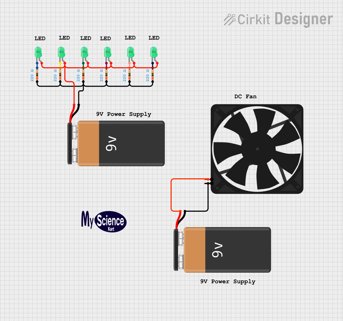
The circuit described in the provided design consists of a simple power supply and load configuration. It includes a fan, multiple LEDs with current-limiting resistors, and two 9V batteries. The fan is directly connected to one of the batteries, while the LEDs are connected in parallel, each with its own resistor in series, to the other battery. There are no microcontrollers or embedded code associated with this circuit.
Component List
Fan
- Description: A basic cooling fan.
- Pins: GND, 5V
9V Battery
- Description: Standard 9V battery providing power to the circuit.
- Pins: -, +
LED: Two Pin (green)
- Description: A green light-emitting diode (LED) used as an indicator or for illumination.
- Pins: cathode, anode
Resistor
- Description: A resistor with a resistance value of 220 Ohms, used to limit current to the LEDs.
- Pins: pin1, pin2
- Properties: Resistance: 220 Ohms
Logo
- Description: A graphical representation or branding element, not electrically functional.
Comment
- Description: A non-functional component used for adding notes or comments to the circuit design.
Wiring Details
Fan
- GND: Connected to the negative terminal (-) of one 9V battery.
- 5V: Connected to the positive terminal (+) of the same 9V battery.
9V Battery (for LEDs)
- +: Connected to the anode of all green LEDs.
- -: Connected to pin1 of all resistors.
LED: Two Pin (green)
- Anode: Connected to the positive terminal (+) of the 9V battery dedicated to the LEDs.
- Cathode: Connected to pin2 of its corresponding resistor.
Resistor
- Pin1: Connected to the negative terminal (-) of the 9V battery dedicated to the LEDs.
- Pin2: Connected to the cathode of its corresponding green LED.
Documented Code
There is no embedded code provided for this circuit as there are no microcontroller components included in the design.
This documentation provides an overview of the circuit components and their connections. It should be used as a reference for building or analyzing the circuit.