Arduino Mega 2560 Controlled Lighting and Display System with Rotary Encoder and Dual Servos
Circuit Documentation
Summary
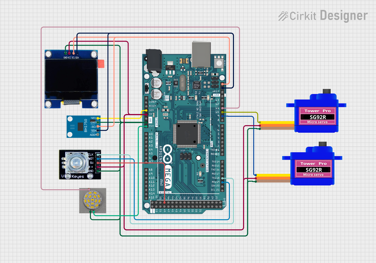
This document provides a detailed overview of a circuit that includes an Arduino Mega 2560 microcontroller as the central processing unit, interfaced with various peripherals including a BH1750 light sensor, two SG92R servomotors, an OLED 1.3" display, a rotary encoder, and an LED. The circuit is designed to leverage the Arduino's I/O capabilities to interact with these components, which are connected via digital and analog interfaces. The microcontroller is programmed to control and communicate with these devices, forming a system capable of sensing, actuating, and displaying information.
Component List
Arduino Mega 2560
- Microcontroller board based on the ATmega2560
- Offers 54 digital input/output pins, 16 analog inputs, 4 UARTs, a 16 MHz crystal oscillator, a USB connection, a power jack, an ICSP header, and a reset button.
BH1750
- A digital light sensor that provides an ambient light measurement in lux.
- Communicates via I2C interface.
Servomotor SG92R (2 units)
- Small and lightweight servomotors for precise angular positioning.
- Operates on PWM signals for control.
OLED 1.3"
- A small display module for visual output.
- Uses I2C for communication.
Rotary Encoder
- An input device that provides feedback on rotation through digital signals.
- Includes a push-button switch.
LED
- A basic light-emitting diode for visual indication.
- Can be controlled via PWM for brightness adjustment.
Wiring Details
Arduino Mega 2560
3V3connected to BH1750 VCC5Vconnected to VCC of both Servomotor SG92Rs, OLED 1.3", and Rotary EncoderGNDconnected to GND of all componentsVINconnected to LED VCCD19/RX1connected to Rotary Encoder DTD18/TX1connected to Rotary Encoder CLKD9 PWMconnected to Servomotor SG92R SIG (first unit)D10 PWMconnected to Servomotor SG92R SIG (second unit)D11 PWMconnected to LED PWMSDAconnected to BH1750 SDA, OLED 1.3" SDASCLconnected to BH1750 SCL, OLED 1.3" SCLD48connected to Rotary Encoder SW
BH1750
VCCconnected to Arduino Mega 2560 3V3GNDconnected to common groundSCLconnected to Arduino Mega 2560 SCLSDAconnected to Arduino Mega 2560 SDA
Servomotor SG92R (First Unit)
SIGconnected to Arduino Mega 2560 D9 PWMVCCconnected to Arduino Mega 2560 5VGNDconnected to common ground
Servomotor SG92R (Second Unit)
SIGconnected to Arduino Mega 2560 D10 PWMVCCconnected to Arduino Mega 2560 5VGNDconnected to common ground
OLED 1.3"
GNDconnected to common groundVCCconnected to Arduino Mega 2560 5VSCLconnected to Arduino Mega 2560 SCLSDAconnected to Arduino Mega 2560 SDA
Rotary Encoder
clkconnected to Arduino Mega 2560 D18/TX1dtconnected to Arduino Mega 2560 D19/RX1swconnected to Arduino Mega 2560 D48gndconnected to common ground+connected to Arduino Mega 2560 5V
LED
VCCconnected to Arduino Mega 2560 VINGNDconnected to common groundPWMconnected to Arduino Mega 2560 D11 PWM
Documented Code
Arduino Mega 2560 Code (sketch.ino)
void setup() {
  // put your setup code here, to run once:

}

void loop() {
  // put your main code here, to run repeatedly:

}
Note: The provided code is a template and does not include specific functionality. It should be populated with setup and loop routines to control the connected components based on the requirements of the application.