
Wi-Fi Controlled Robotic Car with ESP32-CAM and L298N Motor Driver
View and Edit Project In Cirkit Designer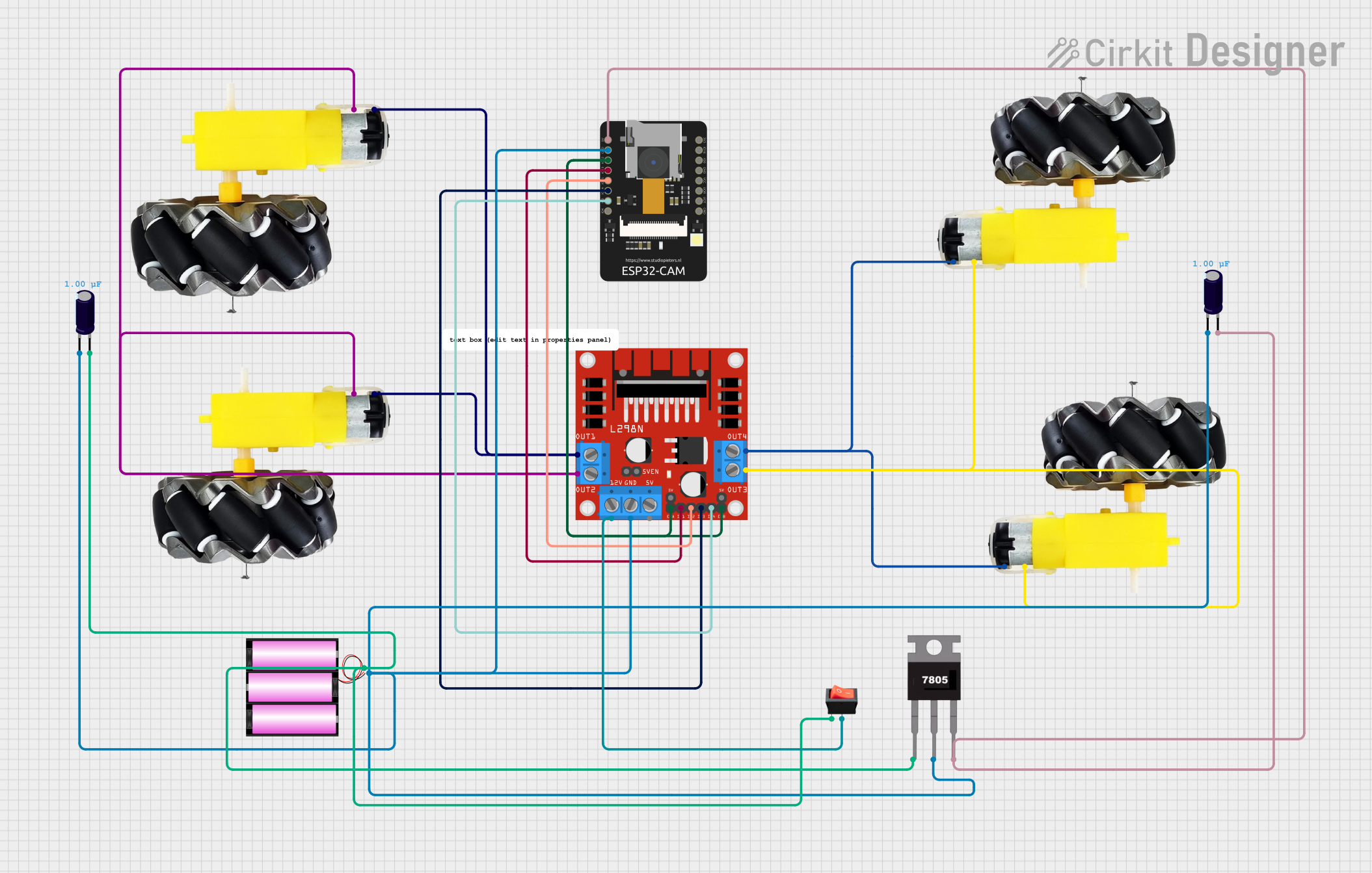
Circuit Documentation
Summary
This document provides a detailed overview of a circuit designed to control multiple motors using an L298N DC motor driver and an ESP32-CAM microcontroller. The circuit is powered by a 12V battery and includes various components such as electrolytic capacitors, a 7805 voltage regulator, and a rocker switch for power control.
Component List
Motor and Wheels
- Description: Motor and wheel assembly
- Pins: VCC, GND
L298N DC Motor Driver
- Description: Dual H-Bridge motor driver
- Pins: OUT1, OUT2, 12V, GND, 5V, OUT3, OUT4, 5V-ENA-JMP-I, 5V-ENA-JMP-O, +5V-J1, +5V-J2, ENA, IN1, IN2, IN3, IN4, ENB
Electrolytic Capacitor
- Description: Capacitor for smoothing voltage
- Pins: +, -
- Properties: Capacitance: 1 µF
ESP32-CAM
- Description: Microcontroller with camera module
- Pins: 5V, GND, IO12, IO13, IO15, IO14, IO2, IO4, VOT, VOR, VCC, IO0, IO16, 3V3
7805 Voltage Regulator
- Description: 5V voltage regulator
- Pins: Vin, Gnd, Vout
Battery 12V
- Description: 12V power source
- Pins: +, -
Rocker Switch
- Description: On/Off switch
- Pins: Input, Output
Comment
- Description: Placeholder for comments
- Pins: None
Wiring Details
Motor and Wheels
VCC connected to:
- VCC of another motor and wheels
- OUT4 of L298N DC motor driver
GND connected to:
- GND of another motor and wheels
- OUT3 of L298N DC motor driver
L298N DC Motor Driver
- OUT1 connected to VCC of motor and wheels
- OUT2 connected to GND of motor and wheels
- OUT3 connected to GND of motor and wheels
- OUT4 connected to VCC of motor and wheels
- 12V connected to output of rocker switch
- GND connected to:
- GND of electrolytic capacitor
- GND of ESP32-CAM
- Gnd of 7805 voltage regulator
- ENA connected to ENB and IO12 of ESP32-CAM
- IN1 connected to IO13 of ESP32-CAM
- IN2 connected to IO15 of ESP32-CAM
- IN3 connected to IO14 of ESP32-CAM
- IN4 connected to IO2 of ESP32-CAM
Electrolytic Capacitor
- + connected to:
-
- of another electrolytic capacitor
- 5V of ESP32-CAM
- Vout of 7805 voltage regulator
-
- - connected to:
-
- of another electrolytic capacitor
-
- of battery 12V
- GND of L298N DC motor driver
- GND of ESP32-CAM
- Gnd of 7805 voltage regulator
-
ESP32-CAM
- 5V connected to + of electrolytic capacitor
- GND connected to GND of electrolytic capacitor
- IO12 connected to ENA and ENB of L298N DC motor driver
- IO13 connected to IN1 of L298N DC motor driver
- IO15 connected to IN2 of L298N DC motor driver
- IO14 connected to IN3 of L298N DC motor driver
- IO2 connected to IN4 of L298N DC motor driver
7805 Voltage Regulator
- Vin connected to + of battery 12V
- Gnd connected to GND of electrolytic capacitor
- Vout connected to + of electrolytic capacitor
Battery 12V
- + connected to:
-
- of electrolytic capacitor
- input of rocker switch
- Vin of 7805 voltage regulator
-
- - connected to:
-
- of electrolytic capacitor
- GND of L298N DC motor driver
- GND of ESP32-CAM
- Gnd of 7805 voltage regulator
-
Rocker Switch
- Input connected to + of battery 12V
- Output connected to 12V of L298N DC motor driver
Documented Code
No code provided for this circuit.
This document provides a comprehensive overview of the circuit, including a summary, component list, wiring details, and code documentation. Each section is designed to offer clear and concise information to facilitate understanding and replication of the circuit.