Arduino UNO Based Hall Effect Sensor Interface with LCD Display

Circuit Documentation
Summary
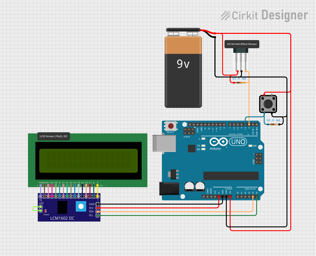
This circuit integrates various components, including an LCM1602 IIC module, an Arduino UNO microcontroller, a Hall sensor, a tactile switch, an LCD 16x2 display compatible with Wokwi, a 9V battery, and resistors. The LCM1602 IIC module is interfaced with the Arduino UNO to facilitate communication via the I2C protocol. The Hall sensor and tactile switch are connected to the Arduino's digital pins and are likely used for input sensing. The 9V battery powers the circuit, with resistors providing necessary voltage drops or pull-up configurations. The LCD display is used for visual output.
Component List
LCM1602 IIC
- A module that provides an I2C interface for LCDs.
Arduino UNO
- A microcontroller board based on the ATmega328P, with digital and analog I/O pins.
Hall Sensor
- A magnetic field sensor that outputs a voltage corresponding to the magnetic field strength.
Tactile Switch Buttons - 12mm Square
- A simple push-button switch for user input.
LCD 16x2 (Wokwi Compatible)
- A 16-character by 2-line liquid crystal display for showing text or numbers.
9V Battery
- A standard 9V battery used to power the circuit.
Resistor (10k Ohms)
- A passive component used to limit current or provide a voltage drop.
Wiring Details
LCM1602 IIC
- GND: Connected to Arduino UNO GND.
- VCC: Connected to Arduino UNO 5V.
- SDA: Connected to Arduino UNO A4.
- SCL: Connected to Arduino UNO A5.
- LED_A and LED_B: Interconnected.
Arduino UNO
- GND: Common ground for the circuit.
- 5V: Provides power to the LCM1602 IIC.
- A4 (SDA): I2C data line connected to LCM1602 IIC SDA.
- A5 (SCL): I2C clock line connected to LCM1602 IIC SCL.
- Vin: Connected to the positive side of the 9V battery through a resistor.
- D2: Connected to the Hall sensor signal output through a resistor.
- D3: Connected to one side of the tactile switch, other side connected to ground through a resistor.
Hall Sensor
- -: Connected to the negative side of the 9V battery.
- +: Connected to the positive side of the 9V battery through a resistor.
- S: Signal output connected to Arduino UNO D2 through a resistor.
Tactile Switch Buttons - 12mm Square
- One side connected to Arduino UNO D3 through a resistor.
- Other side connected to ground.
LCD 16x2 (Wokwi Compatible)
- Interconnected with the LCM1602 IIC module for display control.
9V Battery
- +: Connected to Arduino UNO Vin and Hall sensor + through a resistor.
- -: Connected to Arduino UNO GND and Hall sensor -.
Resistor (10k Ohms)
- Used in series with the 9V battery for the Hall sensor and Arduino UNO Vin.
- Used as a pull-down for the tactile switch and pull-up for the Hall sensor signal line.
Documented Code
Arduino UNO Code (sketch.ino)
void setup() {
  // put your setup code here, to run once:

}

void loop() {
  // put your main code here, to run repeatedly:

}
This code template provides the basic structure for an Arduino sketch, with setup() function to initialize settings and loop() function to contain the main logic that will run continuously. The actual implementation details need to be filled in based on the specific requirements of the circuit's functionality.