Cirkit Designer
Your all-in-one circuit design IDE
Home /
Project Documentation
Arduino Nano-Controlled Lighting System with Gesture and Sound Interaction

Circuit Documentation
Summary
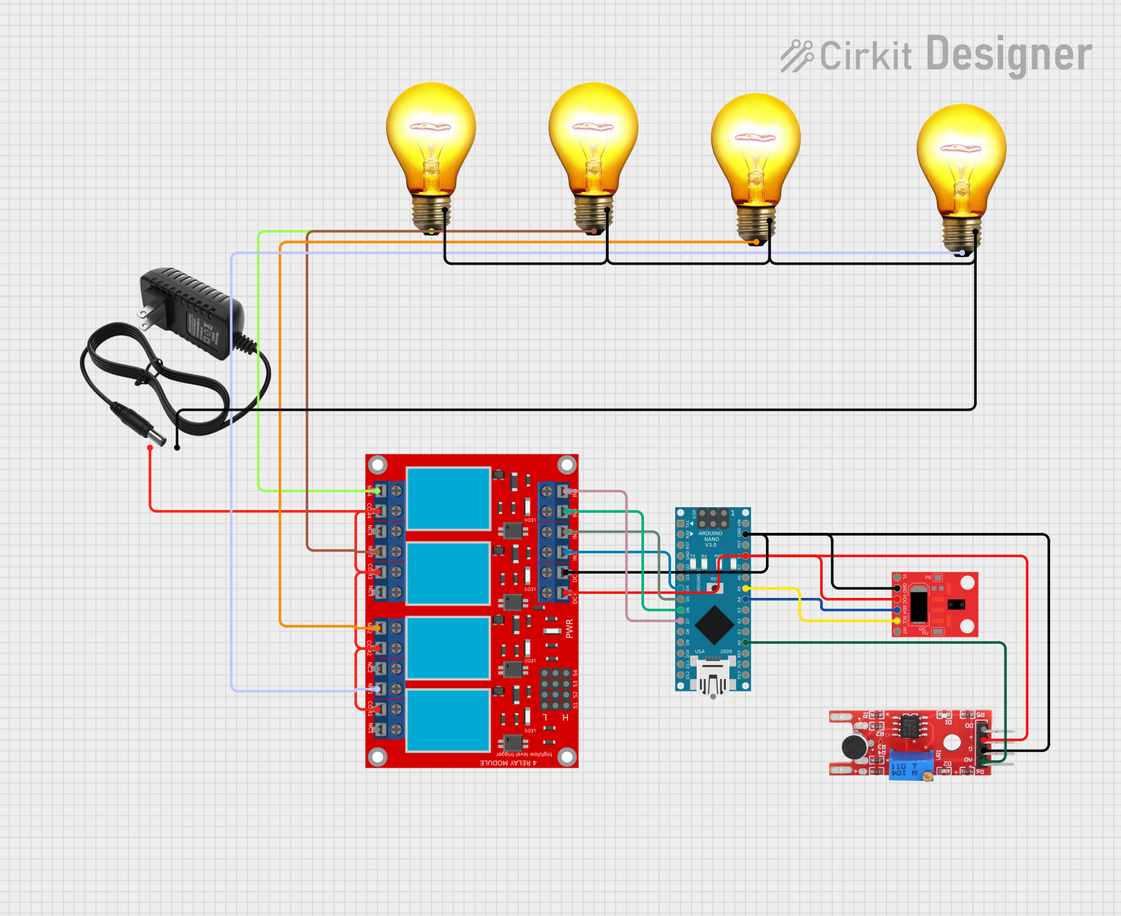
This circuit is designed to interface an APDS-9960 RGB and Gesture Sensor and a KY-038 sensor module with an Arduino Nano microcontroller. The circuit also includes a 4-channel relay module that controls four AC bulbs, powered by a 12V power supply. The Arduino Nano is responsible for processing the sensor inputs and controlling the relay module, which in turn switches the AC bulbs on and off.
Component List
APDS-9960 RGB and Gesture Sensor
- Pins: VL, GND, VCC, SDA, SCL, INT
- Description: A sensor that detects color, ambient light, and gestures.
KY-038
- Pins: +, G, A0, D0
- Description: A sound detection sensor module with digital and analog outputs.
Arduino Nano
- Pins: D1/TX, D0/RX, RESET, GND, D2, D3, D4, D5, D6, D7, D8, D9, D10, D11/MOSI, D12/MISO, VIN, 5V, A7, A6, A5, A4, A3, A2, A1, A0, AREF, 3V3, D13/SCK
- Description: A compact microcontroller board based on the ATmega328P.
12V Power Supply
- Pins: +, -
- Description: Provides a 12V power source for the circuit.
4 Channel Relay Module
- Pins: N.O. 1-4, COM 1-4, N.C. 1-4, Pin 13-24, VCC+, VCC-, IN 1-4
- Description: A module that allows for controlling high power devices with low power signals from the microcontroller.
AC Bulbs (x4)
- Pins: P, N
- Description: Standard AC bulbs that can be switched on and off by the relay module.
Wiring Details
APDS-9960 RGB and Gesture Sensor
- VL: Not connected
- GND: Connected to Arduino Nano GND
- VCC: Connected to Arduino Nano 5V
- SDA: Connected to Arduino Nano A4
- SCL: Connected to Arduino Nano A5
- INT: Not connected
KY-038
- +: Connected to Arduino Nano 5V
- G: Connected to Arduino Nano GND
- A0: Connected to Arduino Nano A0
- D0: Not connected
Arduino Nano
- A4: Connected to APDS-9960 SDA
- A5: Connected to APDS-9960 SCL
- A0: Connected to KY-038 A0
- D4: Connected to Relay Module IN 1
- D5: Connected to Relay Module IN 2
- D6: Connected to Relay Module IN 3
- D7: Connected to Relay Module IN 4
- 5V: Connected to APDS-9960 VCC and KY-038 +
- GND: Connected to APDS-9960 GND and KY-038 G
12V Power Supply
- +: Connected to Relay Module COM 1-4
- -: Connected to AC Bulbs N
4 Channel Relay Module
- VCC+: Connected to Arduino Nano 5V
- VCC- (GND): Connected to Arduino Nano GND
- IN 1: Connected to Arduino Nano D4
- IN 2: Connected to Arduino Nano D5
- IN 3: Connected to Arduino Nano D6
- IN 4: Connected to Arduino Nano D7
- COM 1-4: Connected to 12V Power Supply +
- N.O. 1: Connected to AC Bulb P (Instance 1)
- N.O. 2: Connected to AC Bulb P (Instance 2)
- N.O. 3: Connected to AC Bulb P (Instance 3)
- N.O. 4: Connected to AC Bulb P (Instance 4)
AC Bulbs
- P (Instance 1): Connected to Relay Module N.O. 1
- P (Instance 2): Connected to Relay Module N.O. 2
- P (Instance 3): Connected to Relay Module N.O. 3
- P (Instance 4): Connected to Relay Module N.O. 4
- N: Connected to 12V Power Supply -
Documented Code
Arduino Nano Code (sketch.ino)
void setup() {
  // put your setup code here, to run once:

}

void loop() {
  // put your main code here, to run repeatedly:

}
Note: The provided code is a template and does not contain any functional code to control the circuit. The user must implement the setup and loop functions to initialize the sensors, read their values, and control the relay module accordingly.