
Arduino UNO Based Environmental Monitoring and Control System
View and Edit Project In Cirkit Designer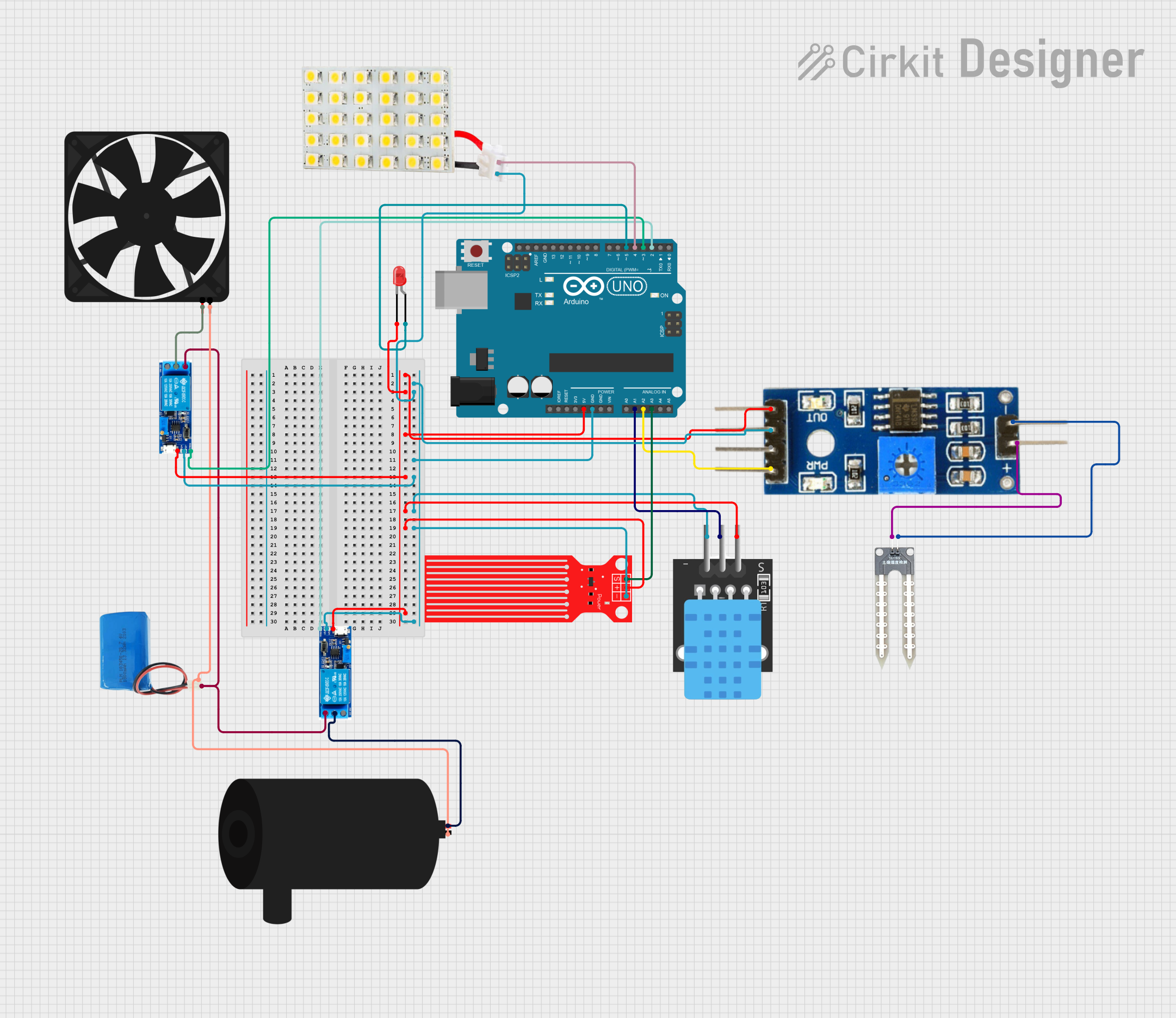
Circuit Documentation
Summary
This circuit is designed to interface various sensors and actuators with an Arduino UNO microcontroller. The circuit includes temperature and water level sensors, a soil moisture module, a water pump, a fan, LED indicators, and relay modules for controlling high-power devices. The Arduino UNO serves as the central processing unit, reading sensor data and controlling the actuators based on programmed logic.
Component List
Arduino UNO
- Microcontroller board based on the ATmega328P
- It has 14 digital input/output pins, 6 analog inputs, a 16 MHz quartz crystal, a USB connection, a power jack, an ICSP header, and a reset button.
TEMP (Temperature Sensor)
- Measures ambient temperature
- Typically has a digital output that interfaces with a microcontroller.
Water Pump
- An electromechanical device used to move water through the system.
Water Sensor
- Detects the presence of water in the environment.
Water Level Sensor
- Measures the level of water in a container or environment.
Fan
- An electric device used to create airflow.
LED: Two Pin (red)
- A red light-emitting diode used as an indicator.
LED Board
- A board with one or more LEDs, used for indication or illumination.
Soil Moisture Module
- Measures the moisture content in the soil.
Relay Module 5v-30v (Two instances)
- An electrically operated switch that allows a low-power circuit to control a high-power circuit.
5v Battery
- Provides a 5V power supply to the circuit.
Wiring Details
Arduino UNO
- 5V: Connected to the 5V power bus
- GND: Connected to the ground bus
- A1: Connected to TEMP sensor
- A2: Connected to Soil Moisture Module (Analog)
- A3: Connected to Water Level Sensor (SIG)
- D5: Connected to LED (anode)
- D4: Connected to LED Board (VCC)
- D3: Connected to Relay Module (trigger)
- D2: Connected to another Relay Module (trigger)
TEMP (Temperature Sensor)
- 5V: Connected to the 5V power bus
- D3: Connected to Arduino UNO (A1)
- GND: Connected to the ground bus
Water Pump
- Positive: Connected to Relay Module (common contact)
- Negative: Connected to the ground bus
Water Sensor
- +: Connected to Soil Moisture Module (positive)
- -: Connected to Soil Moisture Module (negative)
Water Level Sensor
- SIG: Connected to Arduino UNO (A3)
- VCC: Connected to the 5V power bus
- GND: Connected to the ground bus
Fan
- 5V: Connected to Relay Module (common contact)
- GND: Connected to the ground bus
LED: Two Pin (red)
- Cathode: Connected to the 5V power bus
- Anode: Connected to Arduino UNO (D5)
LED Board
- VCC: Connected to Arduino UNO (D4)
- GND: Connected to the ground bus
Soil Moisture Module
- Positive: Connected to Water Sensor (+)
- Negative: Connected to Water Sensor (-)
- Analog: Connected to Arduino UNO (A2)
- Digital: Not connected
- Ground: Connected to the ground bus
- VCC: Connected to the 5V power bus
Relay Module 5v-30v
- Common Contact: Connected to Water Pump (positive) and Fan (5V)
- Normally Open: Connected to 5v Battery (positive)
- Normally Closed: Not connected
- Trigger: Connected to Arduino UNO (D3 or D2)
- V-: Connected to the ground bus
- V+: Connected to the 5V power bus
5v Battery
- Positive: Connected to Relay Modules (normally open)
- Negative: Connected to the ground bus
Documented Code
Arduino UNO Code (sketch.ino)
void setup() {
  // put your setup code here, to run once:

}

void loop() {
  // put your main code here, to run repeatedly:

}
Additional Notes (documentation.txt)
No additional code documentation was provided.