ESP32-Based Interactive Audio Player with LCD Display and Battery Management
Circuit Documentation
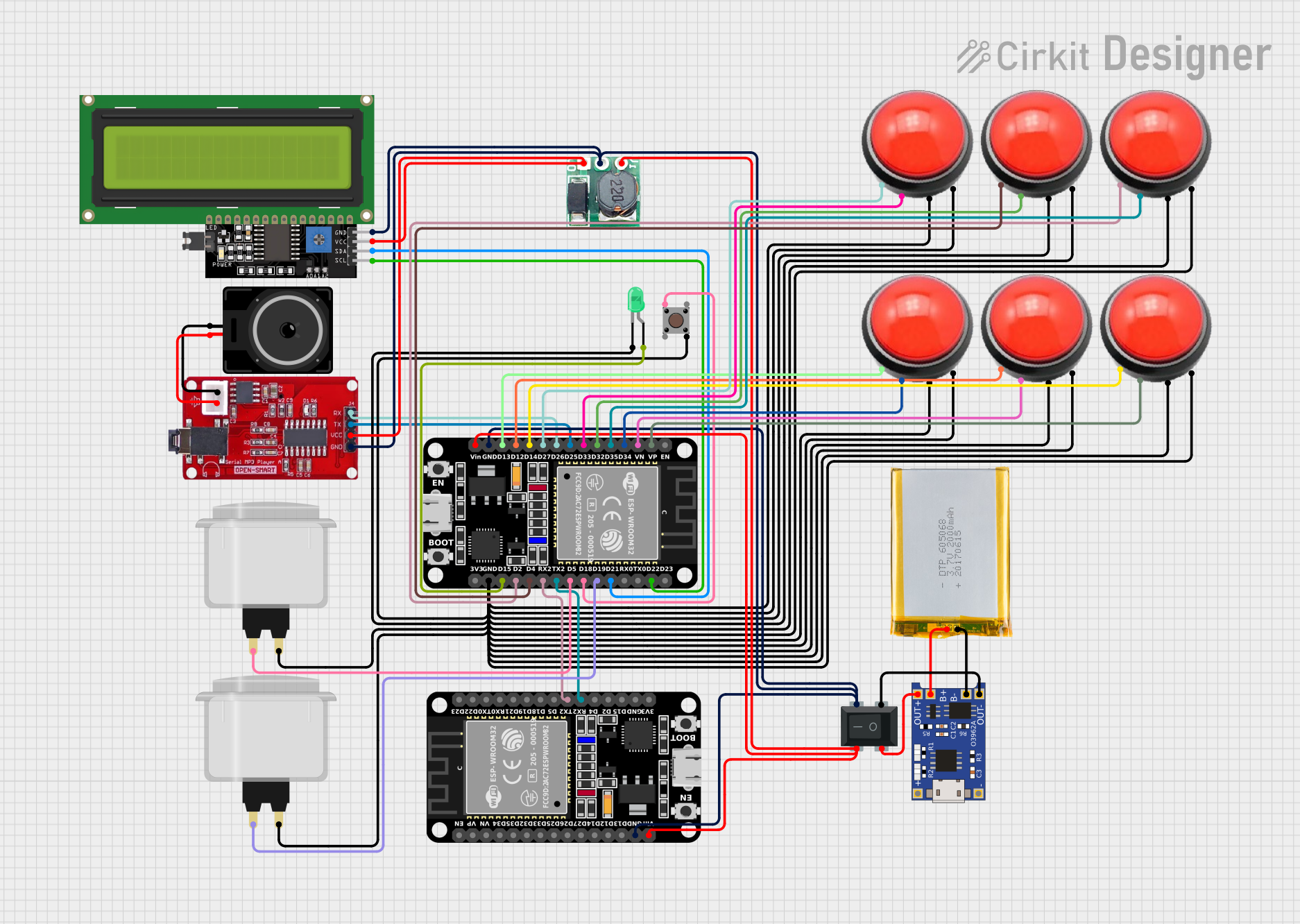
Summary
This circuit integrates various components including microcontrollers, input devices, power management modules, and output devices to form a functional electronic system. The primary microcontroller is an ESP32, which interfaces with a Serial MP3 Player, an LCD Display, and multiple ArcBtnR buttons. The circuit is powered by a 2000mAh battery, managed by a TP4056 charging module, and a Step Up Boost converter to regulate the voltage. The system also includes a pushbutton, a green LED, and a loudspeaker for user interaction and feedback.
Component List
Microcontrollers
- ESP32 (30 pin): A powerful microcontroller with Wi-Fi and Bluetooth capabilities, featuring a variety of digital and analog pins for interfacing with other components.
Input Devices
- Pushbutton: A simple switch that connects two pins when pressed, used for user input.
- ArcBtnR: A button with integrated LED, used for user input and providing visual feedback.
- Arcade Button (white): A large, durable button typically used in arcade machines, also for user input.
Output Devices
- Serial MP3 Player: A module capable of playing MP3 files from an SD card, interfaced via serial communication.
- LCD Display 16x4 I2C: A liquid crystal display with an I2C interface, used to show text or numbers.
- Loudspeaker: An audio output device for playing sounds or music.
- LED: Two Pin (green): A simple light-emitting diode for providing visual feedback.
Power Management
- TP4056: A lithium battery charging module that manages charging and protection of the battery.
- Step Up Boost 3v- 5v: A voltage booster that steps up the input voltage to a higher output voltage.
- 2000mAh Battery: A rechargeable lithium-ion battery providing power to the circuit.
- RockerSwitch4Pin: A switch used to control the power flow in the circuit.
Wiring Details
ESP32 (30 pin)
- EN, VP, VN, D34, D35, D32, D33, D25, D26, D27, D14, D12, D13, GND, Vin, D23, D22, TX0, RX0, D21, D19, D18, D5, TX2, RX2, D4, D2, D15, 3V3
Serial MP3 Player
- RX: Connected to ESP32 D26
- TX: Connected to ESP32 D25
- VCC: Connected to Step Up Boost Vo
- GND: Connected to common ground
Pushbutton
- Pin 3 (out), Pin 4 (out), Pin 1 (in), Pin 2 (in)
TP4056
- OUT-, B-, B+, OUT+, IN-, IN+
LED: Two Pin (green)
- Cathode: Connected to common ground
- Anode: Connected to ESP32 D15
ArcBtnR
- VCC_LED, GND_LED, VCC_BTN, GND_BTN
Step Up Boost 3v- 5v
- Vi: Connected to RockerSwitch4Pin 3
- GND: Connected to common ground
- Vo: Connected to Serial MP3 Player VCC and LCD Display VCC
2000mAh Battery
- VCC: Connected to TP4056 B+
- GND: Connected to TP4056 B-
LCD Display 16x4 I2C
- SCL: Connected to ESP32 D22
- SDA: Connected to ESP32 D21
- VCC: Connected to Step Up Boost Vo
- GND: Connected to common ground
Loudspeaker
- Pin1, Pin2: Connected to Serial MP3 Player GND and VCC respectively
RockerSwitch4Pin
- 1, 3, 2, 4
Documented Code
Microcontroller: ESP32 (30 pin)
File: sketch.ino
void setup() {
  // put your setup code here, to run once:

}

void loop() {
  // put your main code here, to run repeatedly:

}
File: documentation.txt
(No additional documentation provided)
Please note that the code provided is a template and does not contain any functional code specific to the circuit's operation. Additional programming will be required to control the components and achieve the desired functionality.