Arduino-Based Smart Water Level Monitoring and Control System
Circuit Documentation
Summary
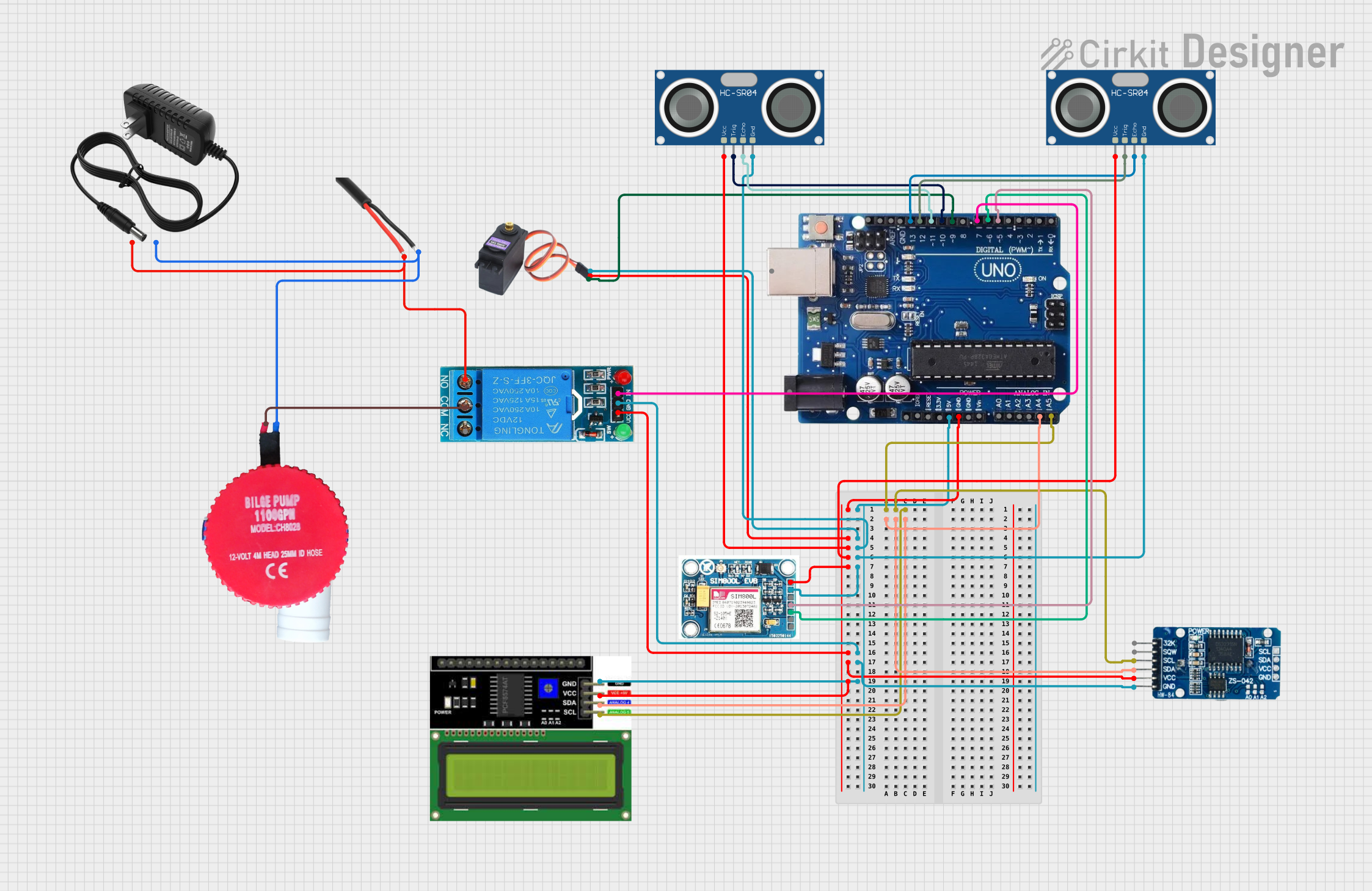
The circuit in question appears to be a complex system involving multiple Arduino Uno R3 boards interfaced with various sensors, actuators, and modules. The system includes ultrasonic sensors (HC-SR04) for distance measurement, a real-time clock module (RTC DS3231) for timekeeping, a servo motor (MG996R), a GSM module (SIM 800L V2.0) for cellular communication, an LCD display with I2C interface for user interaction, a relay module for controlling high-power devices, and a bilge pump for water displacement. The circuit is powered by a 12V power supply, and an AC wire is used to connect the relay to the mains power.
Component List
Arduino Uno R3: A microcontroller board based on the ATmega328P. It has 14 digital input/output pins, 6 analog inputs, a USB connection, a power jack, an ICSP header, and a reset button.
HC-SR04 Ultrasonic Sensor: An ultrasonic distance sensor that provides 2cm to 400cm of non-contact measurement functionality with a ranging accuracy of up to 3mm.
RTC DS3231: A real-time clock module that provides accurate timekeeping with a temperature-compensated crystal oscillator and I2C interface.
MG996R: A high-torque digital servo motor that can rotate approximately 120 degrees (60 in each direction).
SIM 800L V2.0 GSM: A GSM/GPRS module that allows for cellular communication including SMS and data.
LCD I2C Display: A liquid crystal display that uses the I2C communication protocol for displaying text and numbers.
12V SINGLE CHANNEL RELAY: A relay module that can be used to control high voltage/high current devices.
12v power supply: A power supply unit that provides a 12V output.
Bilge Pump 12V: A pump used for removing bilge water.
AC Wire: A wire used to connect devices to the mains AC power.
Wiring Details
Arduino Uno R3
Digital Pins:
- Pin 13: Connected to HC-SR04 Ultrasonic Sensor (Echo).
- Pin 12: Connected to HC-SR04 Ultrasonic Sensor (Trig).
- Pin 11: Connected to another HC-SR04 Ultrasonic Sensor (Echo).
- Pin 10: Connected to another HC-SR04 Ultrasonic Sensor (Trig).
- Pin 9: Connected to MG996R (Signal).
- Pin 7: Connected to 12V SINGLE CHANNEL RELAY (Input).
- Pin 6: Connected to SIM 800L V2.0 GSM (SIM.RXD).
- Pin 5: Connected to SIM 800L V2.0 GSM (SIM_TXD).
Analog Pins:
- A4/SDA: Connected to RTC DS3231 (SDA) and LCD I2C Display (SDA).
- A5/SCL: Connected to RTC DS3231 (SCL) and LCD I2C Display (SCL).
Power Pins:
- 5V: Connected to MG996R (VCC), both HC-SR04 Ultrasonic Sensors (VCC), SIM 800L V2.0 GSM (5V/4V), 12V SINGLE CHANNEL RELAY (VCC), RTC DS3231 (VCC), and LCD I2C Display (VCC).
- GND: Connected to MG996R (GND), both HC-SR04 Ultrasonic Sensors (GND), SIM 800L V2.0 GSM (GND), 12V SINGLE CHANNEL RELAY (GND), RTC DS3231 (GND), and LCD I2C Display (GND).
HC-SR04 Ultrasonic Sensor
- VCC: Connected to Arduino Uno R3 (5V).
- TRIG: Connected to Arduino Uno R3 (Digital Pin 12 or 10).
- ECHO: Connected to Arduino Uno R3 (Digital Pin 13 or 11).
- GND: Connected to Arduino Uno R3 (GND).
RTC DS3231
- SCL: Connected to Arduino Uno R3 (A5/SCL).
- SDA: Connected to Arduino Uno R3 (A4/SDA).
- VCC: Connected to Arduino Uno R3 (5V).
- GND: Connected to Arduino Uno R3 (GND).
MG996R
- SIG: Connected to Arduino Uno R3 (Digital Pin 9).
- VCC: Connected to Arduino Uno R3 (5V).
- GND: Connected to Arduino Uno R3 (GND).
SIM 800L V2.0 GSM
- SIM_TXD: Connected to Arduino Uno R3 (Digital Pin 5).
- SIM.RXD: Connected to Arduino Uno R3 (Digital Pin 6).
- 5V/4V: Connected to Arduino Uno R3 (5V).
- GND: Connected to Arduino Uno R3 (GND).
LCD I2C Display
- SDA: Connected to Arduino Uno R3 (A4/SDA).
- SCL: Connected to Arduino Uno R3 (A5/SCL).
- VCC: Connected to Arduino Uno R3 (5V).
- GND: Connected to Arduino Uno R3 (GND).
12V SINGLE CHANNEL RELAY
- IN: Connected to Arduino Uno R3 (Digital Pin 7).
- VCC: Connected to Arduino Uno R3 (5V).
- GND: Connected to Arduino Uno R3 (GND).
- NO: Connected to 12v power supply (+) and AC Wire (Phase).
- COM: Connected to Bilge Pump 12V (P).
12v power supply
- +: Connected to 12V SINGLE CHANNEL RELAY (NO).
- -: Connected to Bilge Pump 12V (G) and AC Wire (GND).
Bilge Pump 12V
- P: Connected to 12V SINGLE CHANNEL RELAY (COM).
- G: Connected to 12v power supply (-).
AC Wire
- Phase: Connected to 12V SINGLE CHANNEL RELAY (NO).
- GND: Connected to 12v power supply (-).
Documented Code
No code was provided for the microcontrollers in the circuit. Therefore, this section is not applicable. If code becomes available, it should be documented here with appropriate comments and explanations for each function and routine.