
ESP8266 Controlled Environment Monitoring System with I2C LCD Display and Relay Switched Fan
View and Edit Project In Cirkit Designer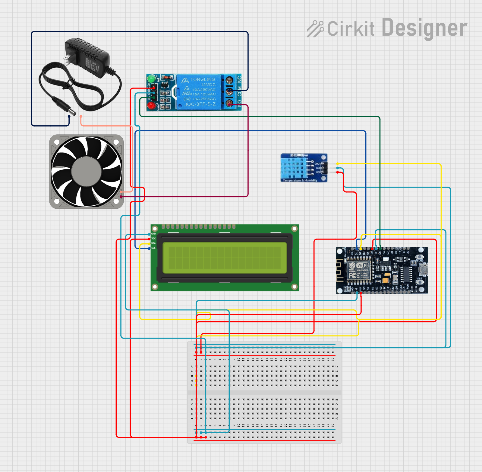
Circuit Documentation
Summary
The circuit in question is designed to interface an ESP8266 microcontroller with a DHT11 temperature and humidity sensor, an I2C LCD 16x2 screen, a 12V single-channel relay, and a 40mm 12V fan. The ESP8266 serves as the central processing unit, reading sensor data from the DHT11 and displaying information on the LCD screen. It also controls the relay, which in turn powers the fan. The 12V power supply provides the necessary voltage for the relay and the fan, while the ESP8266 and other components operate at lower voltages.
Component List
ESP8266
- Description: A Wi-Fi capable microcontroller with multiple GPIO pins.
- Pins: 3V, G (Ground), D0-D8 (Digital pins), A0 (Analog pin), S0-S3 (SPI pins), SC, SK, EN, VIN, RST, VU.
DHT11
- Description: A basic, low-cost digital temperature and humidity sensor.
- Pins: DATA, GND (Ground), VCC (Power).
I2C LCD 16x2 Screen
- Description: A 16x2 character LCD display that uses the I2C communication protocol.
- Pins: SCL (Serial Clock Line), SDA (Serial Data Line), VCC (5V), GND (Ground), VDD, VO, RS, RW, E, D0-D7 (Data pins), BLA, BLK.
12V Single Channel Relay
- Description: An electromechanical switch that allows a low-power signal to control a higher power circuit, in this case, a 12V fan.
- Pins: NC (Normally Closed), COM (Common), NO (Normally Open), IN (Input), GND (Ground), VCC (Power).
40mm Fan 12V
- Description: A standard 40mm fan operating at 12V for cooling purposes.
- Pins: +12V, -12V.
12V Power Supply
- Description: Provides a 12V output to power the relay and the fan.
- Pins: + (Positive), - (Negative).
Wiring Details
ESP8266
- 3V connected to DHT11 VCC.
- G (Ground) connected to DHT11 GND, I2C LCD GND, and 12V Single Channel Relay GND.
- D0-D8 (Digital pins) with D2 connected to I2C LCD SDA and DHT11 DATA, D1 connected to I2C LCD SCL, and D5 connected to 12V Single Channel Relay IN.
- VU (Voltage USB) connected to I2C LCD VCC (5V) and 12V Single Channel Relay VCC.
DHT11
- DATA connected to ESP8266 D2.
- GND connected to ESP8266 G.
- VCC connected to ESP8266 3V.
I2C LCD 16x2 Screen
- SCL connected to ESP8266 D1.
- SDA connected to ESP8266 D2.
- VCC (5V) connected to ESP8266 VU.
- GND connected to ESP8266 G.
12V Single Channel Relay
- NC not connected in this circuit.
- COM connected to 12V Power Supply +.
- NO connected to 40mm Fan 12V +12V.
- IN connected to ESP8266 D5.
- GND connected to ESP8266 G.
- VCC connected to ESP8266 VU.
40mm Fan 12V
- +12V connected to 12V Single Channel Relay NO.
- -12V connected to 12V Power Supply -.
12V Power Supply
-
- connected to 12V Single Channel Relay COM.
-
- connected to 40mm Fan 12V -12V.
Documented Code
Since no code was provided in the input, this section is not applicable. However, typically this section would include the source code for the microcontroller, along with comments explaining the functionality of each part of the code. This would cover initialization, main loop, interrupt service routines, and any other relevant functions or libraries used in the code.