
Arduino Mega 2560-Based Smart Home Automation System with LCD Display and Motor Control
View and Edit Project In Cirkit Designer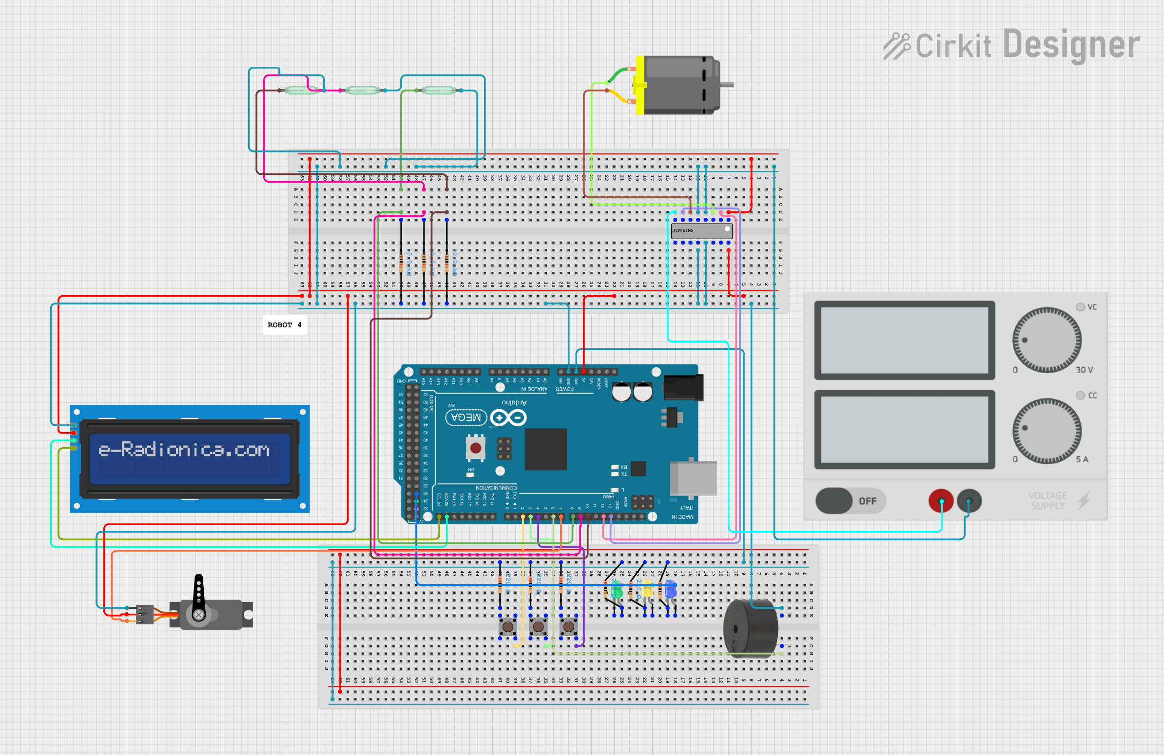
Circuit Documentation
Summary
This circuit is built around an Arduino Mega 2560 microcontroller and includes various components such as pushbuttons, resistors, LEDs, a buzzer, a servo motor, a DC motor, an LCD screen, and a motor driver IC (SN754410). The circuit is designed to interface with these components to perform various tasks, which can be controlled and monitored via the Arduino.
Component List
Arduino Mega 2560
- Description: Microcontroller board based on the ATmega2560.
- Pins: IOREF, RESET, 3V3, 5V, GND, VIN, A0-A15, D0-D53, AREF, SDA, SCL.
Pushbutton
- Description: A simple pushbutton switch.
- Pins: Pin 1 (in), Pin 2 (in), Pin 3 (out), Pin 4 (out).
Resistor (220 Ohms)
- Description: Resistor with a resistance of 220 Ohms.
- Pins: pin1, pin2.
Resistor (10k Ohms)
- Description: Resistor with a resistance of 10k Ohms.
- Pins: pin1, pin2.
Buzzer
- Description: A simple piezoelectric buzzer.
- Pins: PIN, GND.
LED: Two Pin (green)
- Description: Green LED.
- Pins: cathode, anode.
LED: Two Pin (yellow)
- Description: Yellow LED.
- Pins: cathode, anode.
LED: Two Pin (blue)
- Description: Blue LED.
- Pins: cathode, anode.
LCD screen 16x2 I2C
- Description: 16x2 character LCD screen with I2C interface.
- Pins: SCL, SDA, VCC, GND.
Servo
- Description: Servo motor.
- Pins: GND, VCC, PWM.
DC Motor
- Description: Simple DC motor.
- Pins: pin 1, pin 2.
SN754410
- Description: Quadruple half-H driver.
- Pins: 1,2 Enable, 1 In, 1 Out, GND, 2 Out, 2 In, VCC Motor, VCC Logic, 4 In, 4 Out, 3 Out, 3 In, 3,4 Enable.
Power Supply
- Description: Power supply unit.
- Pins: +, -.
Reed Switch
- Description: Magnetic reed switch.
- Pins: pin 1, pin 2.
Wiring Details
Arduino Mega 2560
5V is connected to:
- VCC Logic of SN754410
- VCC of Servo
- VCC of LCD screen 16x2 I2C
- 1,2 Enable of SN754410
GND is connected to:
- pin1 of multiple 220 Ohms resistors
- pin2 of multiple 10k Ohms resistors
- GND of Buzzer
- GND of SN754410
- GND of Servo
- GND of LCD screen 16x2 I2C
-
- of Power Supply
- pin 2 of multiple Reed Switches
D21/SCL is connected to:
- SCL of LCD screen 16x2 I2C
D20/SDA is connected to:
- SDA of LCD screen 16x2 I2C
D2 PWM is connected to:
- Pin 4 (out) of Pushbutton
D3 PWM is connected to:
- Pin 4 (out) of another Pushbutton
D4 PWM is connected to:
- Pin 4 (out) of another Pushbutton
D6 PWM is connected to:
- PIN of Buzzer
D7 PWM is connected to:
- PWM of Servo
D8 PWM is connected to:
- pin1 of a 10k Ohms Resistor
- pin 1 of a Reed Switch
D9 PWM is connected to:
- pin1 of another 10k Ohms Resistor
- pin 1 of another Reed Switch
D10 PWM is connected to:
- pin1 of another 10k Ohms Resistor
- pin 1 of another Reed Switch
D12 PWM is connected to:
- 1 In of SN754410
D13 PWM is connected to:
- 2 In of SN754410
D26 is connected to:
- anode of Blue LED
D24 is connected to:
- anode of Yellow LED
D22 is connected to:
- anode of Green LED
- pin2 of a 220 Ohms Resistor
Pushbutton
Pin 4 (out) is connected to:
- D2 PWM of Arduino Mega 2560
Pin 4 (out) of another Pushbutton is connected to:
- D3 PWM of Arduino Mega 2560
Pin 4 (out) of another Pushbutton is connected to:
- D4 PWM of Arduino Mega 2560
Pin 1 (in) is connected to:
- pin2 of a 220 Ohms Resistor
Pin 1 (in) of another Pushbutton is connected to:
- pin2 of another 220 Ohms Resistor
Pin 1 (in) of another Pushbutton is connected to:
- pin2 of another 220 Ohms Resistor
Resistor (220 Ohms)
pin1 is connected to:
- GND of Arduino Mega 2560
pin2 is connected to:
- Pin 1 (in) of Pushbutton
pin2 of another Resistor is connected to:
- Pin 1 (in) of another Pushbutton
pin2 of another Resistor is connected to:
- Pin 1 (in) of another Pushbutton
pin2 of another Resistor is connected to:
- cathode of Yellow LED
pin2 of another Resistor is connected to:
- cathode of Blue LED
Resistor (10k Ohms)
pin1 is connected to:
- D8 PWM of Arduino Mega 2560
- pin 1 of Reed Switch
pin1 of another Resistor is connected to:
- D9 PWM of Arduino Mega 2560
- pin 1 of another Reed Switch
pin1 of another Resistor is connected to:
- D10 PWM of Arduino Mega 2560
- pin 1 of another Reed Switch
Buzzer
PIN is connected to:
- D6 PWM of Arduino Mega 2560
GND is connected to:
- GND of Arduino Mega 2560
LED: Two Pin (green)
anode is connected to:
- D22 of Arduino Mega 2560
cathode is connected to:
- pin2 of a 220 Ohms Resistor
LED: Two Pin (yellow)
anode is connected to:
- D24 of Arduino Mega 2560
cathode is connected to:
- pin2 of a 220 Ohms Resistor
LED: Two Pin (blue)
anode is connected to:
- D26 of Arduino Mega 2560
cathode is connected to:
- pin2 of a 220 Ohms Resistor
LCD screen 16x2 I2C
SCL is connected to:
- D21/SCL of Arduino Mega 2560
SDA is connected to:
- D20/SDA of Arduino Mega 2560
VCC is connected to:
- 5V of Arduino Mega 2560
GND is connected to:
- GND of Arduino Mega 2560
Servo
PWM is connected to:
- D7 PWM of Arduino Mega 2560
VCC is connected to:
- 5V of Arduino Mega 2560
GND is connected to:
- GND of Arduino Mega 2560
DC Motor
pin 1 is connected to:
- 1 Out of SN754410
pin 2 is connected to:
- 2 Out of SN754410
SN754410
1,2 Enable is connected to:
- 5V of Arduino Mega 2560
1 In is connected to:
- D12 PWM of Arduino Mega 2560
1 Out is connected to:
- pin