
Battery-Powered ESP32-S3 Controlled Servo System with gForceJoint UART
View and Edit Project In Cirkit Designer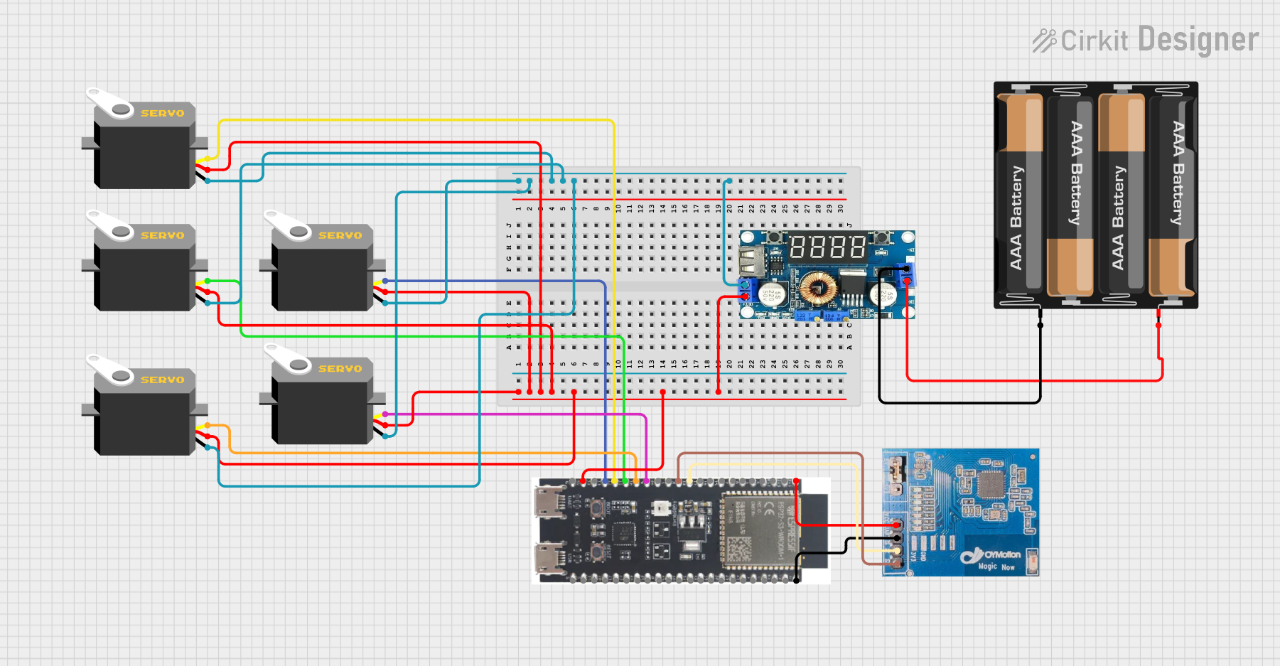
Circuit Documentation
Summary
This circuit consists of an ESP32-S3 microcontroller, multiple servos, a stepdown DC regulator with an LCD display, a 4 x AAA battery mount, and a gForceJoint UART 111 module. The ESP32-S3 controls the servos and communicates with the gForceJoint UART 111 module. The power for the circuit is supplied by the 4 x AAA battery mount, regulated by the stepdown DC regulator.
Component List
Regulator Stepdown DC with LCD Display
- Pins: IN +, IN -, OUT +, OUT -
- Description: A stepdown DC regulator with an LCD display to regulate the voltage from the battery mount.
Servo
- Pins: gnd, vcc, pulse
- Description: A servo motor used for precise control of angular position.
4 x AAA Battery Mount
- Pins: -, +
- Description: A battery holder for four AAA batteries to supply power to the circuit.
ESP32-S3
- Pins: 3v3, EN, GPIO4, GPIO5, GPIO6, GPIO7, GPIO15, GPIO16, GPIO17, GPIO18, GPIO8, GPIO46, GPIO9, GPIO10, GPIO11, GPIO12, GPIO13, GPIO14, 5V, GND, GPIO43, GPIO44, GPIO1, GPIO2, GPIO42, GPIO41, GPIO40, GPIO39, GPIO38, GPIO37, GPIO36, GPIO35, GPIO0, GPIO45, GPIO48, GPIO47, GPIO21, GPIO20, GPIO19
- Description: A powerful microcontroller with multiple GPIO pins for various applications.
gForceJoint UART 111
- Pins: uart, GN, TX, RX
- Description: A UART module for communication with the ESP32-S3.
Wiring Details
Regulator Stepdown DC with LCD Display
- IN + connected to + of the 4 x AAA Battery Mount
- IN - connected to - of the 4 x AAA Battery Mount
- OUT + connected to vcc of all Servos and 5V of the ESP32-S3
- OUT - connected to gnd of all Servos
Servo (5 instances)
- vcc connected to OUT + of the Regulator Stepdown DC with LCD Display
- gnd connected to OUT - of the Regulator Stepdown DC with LCD Display
- pulse connections:
- Servo 1: pulse connected to GPIO9 of the ESP32-S3
- Servo 2: pulse connected to GPIO11 of the ESP32-S3
- Servo 3: pulse connected to GPIO10 of the ESP32-S3
- Servo 4: pulse connected to GPIO12 of the ESP32-S3
- Servo 5: pulse connected to GPIO13 of the ESP32-S3
4 x AAA Battery Mount
- + connected to IN + of the Regulator Stepdown DC with LCD Display
- - connected to IN - of the Regulator Stepdown DC with LCD Display
ESP32-S3
- 5V connected to OUT + of the Regulator Stepdown DC with LCD Display
- GND connected to OUT - of the Regulator Stepdown DC with LCD Display
- GPIO9 connected to pulse of Servo 1
- GPIO11 connected to pulse of Servo 2
- GPIO10 connected to pulse of Servo 3
- GPIO12 connected to pulse of Servo 4
- GPIO13 connected to pulse of Servo 5
- 3v3 connected to uart of the gForceJoint UART 111
- GPIO17 connected to TX of the gForceJoint UART 111
- GPIO18 connected to RX of the gForceJoint UART 111
- GND connected to GN of the gForceJoint UART 111
gForceJoint UART 111
- uart connected to 3v3 of the ESP32-S3
- TX connected to GPIO17 of the ESP32-S3
- RX connected to GPIO18 of the ESP32-S3
- GN connected to GND of the ESP32-S3
Code
No code provided for this circuit.