Arduino-Controlled Robotic Arm with Customizable Servo Routines
Circuit Documentation
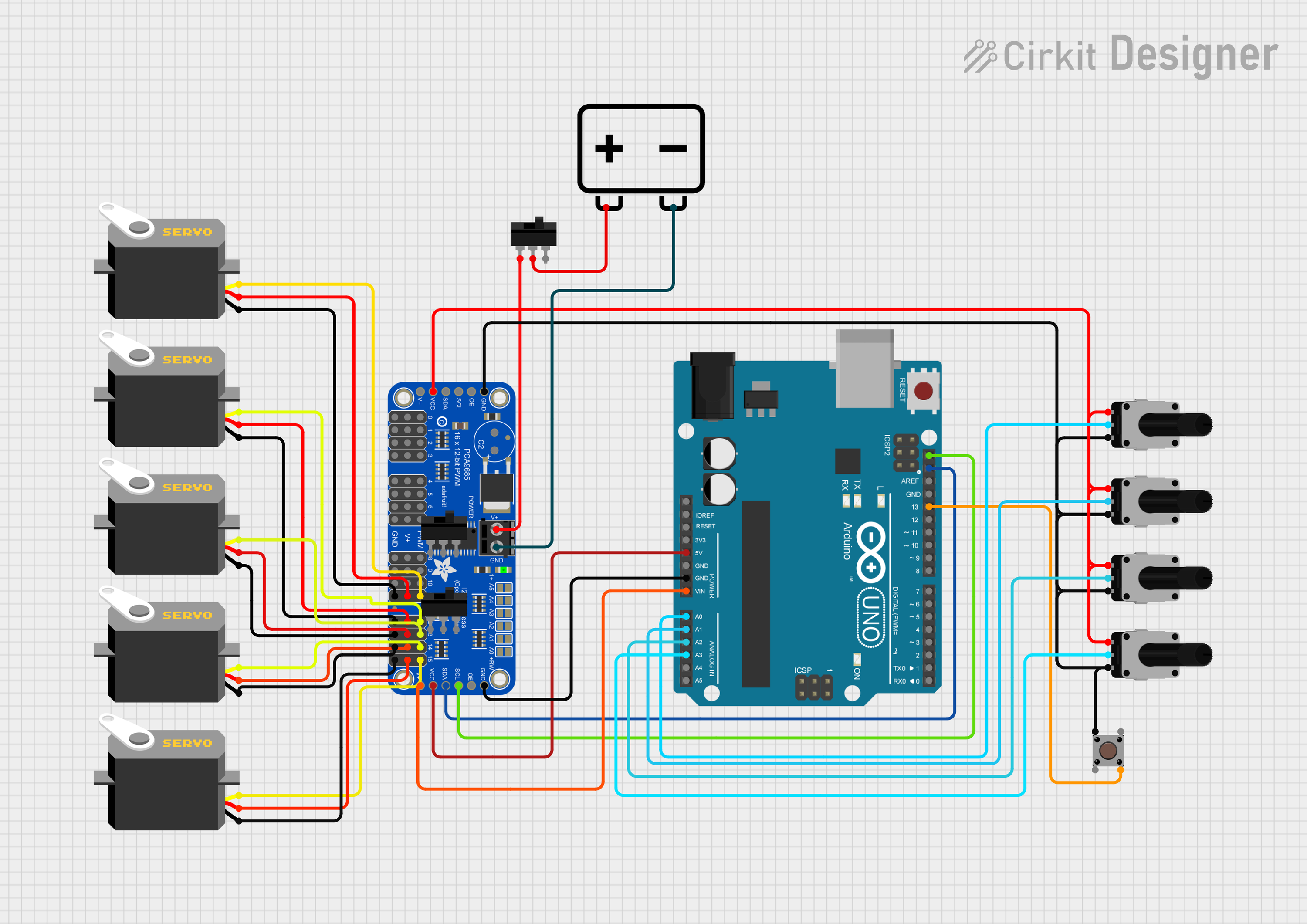
Summary
The circuit in question is designed to control multiple servos using an Arduino UNO and an Adafruit PCA9685 PWM Servo Breakout board. The servos are actuated based on the input from rotary potentiometers and a pushbutton. A toggle switch is used to control the power supply to the PWM breakout board, and a 12V battery provides the power source for the system.
Component List
Arduino UNO
- Microcontroller board based on the ATmega328P
- It has 14 digital input/output pins, 6 analog inputs, a 16 MHz quartz crystal, a USB connection, a power jack, an ICSP header, and a reset button.
Rotary Potentiometer (x4)
- Variable resistor with a knob that can be turned to adjust resistance value.
- Each potentiometer has a resistance of 10,000 Ohms.
Pushbutton
- A simple switch mechanism for controlling some aspect of a machine or a process.
Servo (x5)
- A rotary actuator or linear actuator that allows for precise control of angular or linear position, velocity, and acceleration.
Toggle Switch (x3)
- An electrical switch that is manually actuated by a mechanical lever, handle, or rocking mechanism.
Adafruit PCA9685 PWM Servo Breakout
- A 16-channel, 12-bit PWM Fm+ I2C-bus LED controller ideal for driving servos.
12v Battery
- Provides the power source for the circuit.
Wiring Details
Arduino UNO
Vinconnected to Adafruit PCA9685 PWM Servo Breakout5.0V5Vconnected to Adafruit PCA9685 PWM Servo BreakoutVCCSDAconnected to Adafruit PCA9685 PWM Servo BreakoutSDASCLconnected to Adafruit PCA9685 PWM Servo BreakoutSCLGNDconnected to Adafruit PCA9685 PWM Servo BreakoutGNDA0connected to Rotary Potentiometerwiper(Base)A1connected to Rotary Potentiometerwiper(Shoulder)A2connected to Rotary Potentiometerwiper(Elbow)A3connected to Rotary Potentiometerwiper(Wrist)D13connected to PushbuttonPin 4 (out)
Rotary Potentiometer (x4)
leg1connected to Adafruit PCA9685 PWM Servo BreakoutVCCwiperconnected to Arduino UNOAnalog Pins (A0-A3)leg2connected to Adafruit PCA9685 PWM Servo BreakoutGND
Pushbutton
Pin 1 (in)connected to Adafruit PCA9685 PWM Servo BreakoutGNDPin 4 (out)connected to Arduino UNOD13
Servo (x5)
gndconnected to Adafruit PCA9685 PWM Servo BreakoutGNDvccconnected to Adafruit PCA9685 PWM Servo Breakout5.0Vpulseconnected to Adafruit PCA9685 PWM Servo BreakoutPWMchannels (11-15)
Toggle Switch (x3)
L1connected to Adafruit PCA9685 PWM Servo BreakoutPWRINCOMconnected to 12v Battery+L2not connected
Adafruit PCA9685 PWM Servo Breakout
PWRINconnected to Toggle SwitchL1GNDconnected to 12v Battery-and Arduino UNOGNDVCCconnected to Arduino UNO5Vand Rotary Potentiometerleg1SDAconnected to Arduino UNOSDASCLconnected to Arduino UNOSCLPWMchannels (11-15) connected to Servopulse
12v Battery
+connected to Toggle SwitchCOM-connected to Adafruit PCA9685 PWM Servo BreakoutGND
Documented Code
#include <SoftwareWire.h>
#include <Wire.h>
#include <Adafruit_PWMServoDriver.h>

#define MIN_PULSE_WIDTH       650
#define MAX_PULSE_WIDTH       2350
#define FREQUENCY             50

Adafruit_PWMServoDriver pwm = Adafruit_PWMServoDriver();

const int pinSDA = A4;
const int pinSCL = A5;
SoftwareWire myWire(pinSDA, pinSCL);

int potMuneca = A3;
int potCodo = A2;
int potHombro = A1;
int potBase = A0;

int mano = 11;
int muneca = 12;
int codo = 13;
int hombro = 14;
int base = 15;

const int botonRutina1 = 2;
const int botonRutina2 = 3;
const int botonRutina3 = 4;

int rutinaActual = 0;

void ejecutarRutina();

void setup() {
  myWire.begin();
  Serial.begin(9600);
  delay(5000);

  pwm.begin();
  pwm.setPWMFreq(FREQUENCY);
  pwm.setPWM(11, 0, 90);

  pinMode(13,INPUT_PULLUP);
  pinMode(botonRutina1, INPUT_PULLUP);
  pinMode(botonRutina2, INPUT_PULLUP);
  pinMode(botonRutina3, INPUT_PULLUP);

  Serial.begin(9600);
}

void moveMotor(int controlIn, int motorOut) {
  int pulse_wide, pulse_width, potVal;

  potVal = analogRead(controlIn);

  pulse_wide = map(potVal, 800, 240, MIN_PULSE_WIDTH, MAX_PULSE_WIDTH);
  pulse_width = int(float(pulse_wide) / 1000000 * FREQUENCY * 4096);

  pwm.setPWM(motorOut, 0, pulse_width);
}

void loop() {
  myWire.beginTransmission(0x3C);
  myWire.write(0x00);
  myWire.endTransmission();

  if (digitalRead(botonRutina1) == LOW) {
    rutinaActual = 1;
    delay(200);
  } else if (digitalRead(botonRutina2) == LOW) {
    rutinaActual = 2;
    delay(200);
  } else if (digitalRead(botonRutina3) == LOW) {
    rutinaActual = 3;
    delay(200);
  }

  if (rutinaActual > 0) {
    ejecutarRutina();
  } else {
    moveMotor(potMuneca, muneca);
    moveMotor(potCodo, codo);
    moveMotor(potHombro, hombro);
    moveMotor(potBase, base);
  }
  int gripper = digitalRead(13);
  if(gripper == LOW) {
     pwm.setPWM(mano, 0, 180);
  } else {
     pwm.setPWM(mano, 0, 90);
  }
}

void ejecutarRutina() {
  switch (rutinaActual) {
    case 1:
      pwm.setPWM(mano, 0, 70);
      delay(100);
      pwm.setPWM(muneca, 0, 70);
      delay(100);
      pwm.setPWM(codo, 0, 70);
      delay(100);
      pwm.setPWM(hombro, 0, 70);
      delay(100);
      pwm.setPWM(base, 0, 70);
      delay(100);
      break;

    case 2:
      pwm.setPWM(mano, 0, 35);
      pwm.setPWM(muneca, 0, 35);
      pwm.setPWM(codo, 0, 45);
      pwm.setPWM(hombro, 0, 45);
      pwm.setPWM(base, 0, 45);
      break;

    case 3:
      pwm.setPWM(mano, 0, 120);
      pwm.setPWM(muneca, 0, 120);
      pwm.setPWM(codo, 0, 120);
      pwm.setPWM(hombro, 0, 120);
      pwm.setPWM(base, 0, 120);
      break;

    default:
      rutinaActual = 0;
      break;
  }

  rutinaActual = 0;
}
This code is designed to read the position of four potentiometers and use these values to control the position of servos via the PWM breakout board. Additionally, it includes routines that can be triggered by pressing buttons to move the servos to predefined positions. The moveMotor function maps the potentiometer values to servo positions, and the ejecutarRutina function executes the routines based on the selected routine number.