
Arduino Nano-Based Dual DC Motor Controller with Rotary Encoder and I2C LCD Display
View and Edit Project In Cirkit Designer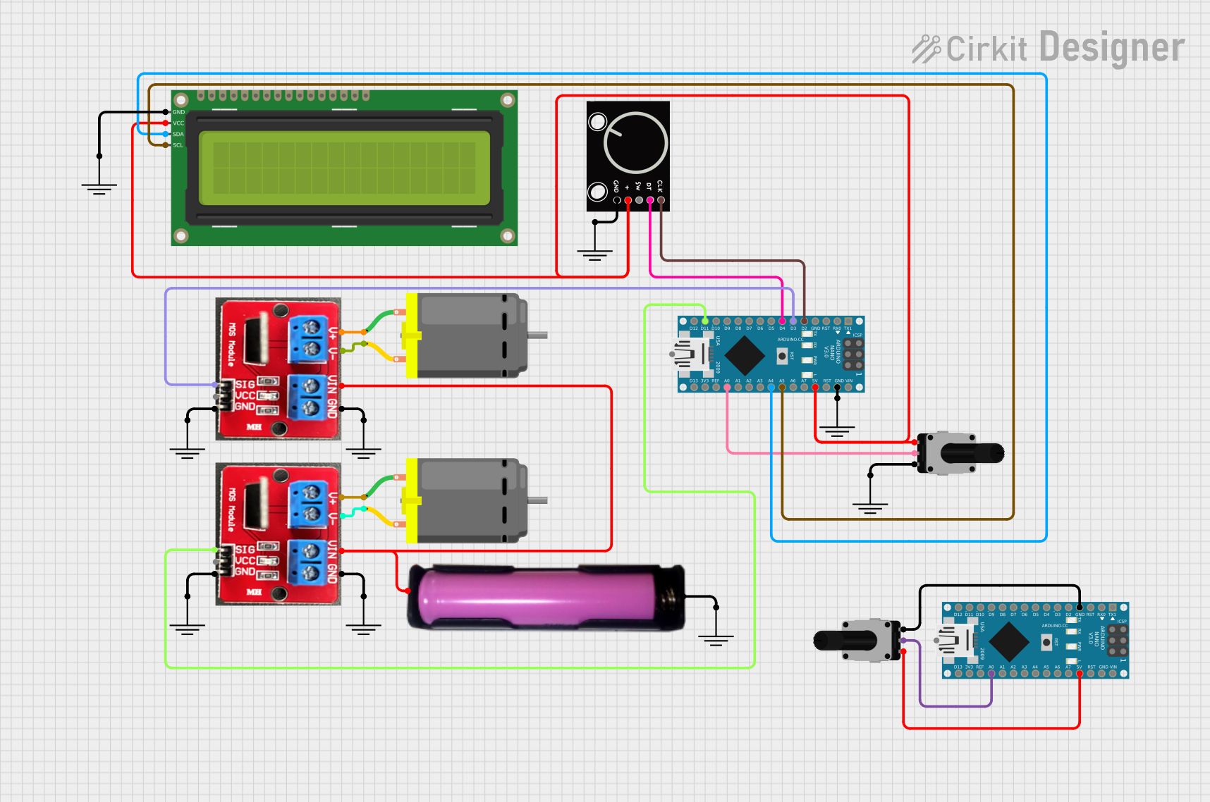
Circuit Documentation
Summary
This circuit involves an Arduino Nano microcontroller interfacing with various components including a rotary encoder, rotary potentiometers, an I2C LCD display, IRF520 PWM modules, and DC motors. The circuit is powered by a 18650 battery in a holder. The Arduino Nano is programmed to control the components based on the inputs received from the rotary encoder and potentiometers, and to display information on the LCD.
Component List
Arduino Nano
- Description: A small, complete, and breadboard-friendly board based on the ATmega328P.
- Pins: D1/TX, D0/RX, RESET, GND, D2, D3, D4, D5, D6, D7, D8, D9, D10, D11/MOSI, D12/MISO, VIN, 5V, A7, A6, A5, A4, A3, A2, A1, A0, AREF, 3V3, D13/SCK
Rotary Encoder
- Description: A device that converts the angular position or motion of a shaft to an analog or digital code.
- Pins: GND, +, SW, DT, CLK
Rotary Potentiometer
- Description: A variable resistor with a resistance of 10k Ohms.
- Pins: leg1, wiper, leg2
16x2 I2C LCD
- Description: A 16x2 character LCD display with I2C interface.
- Pins: GND, VCC, SDA, SCL
IRF520 PWM
- Description: A PWM module based on the IRF520 MOSFET.
- Pins: V+, V-, Vin, GND, SIG, Vcc
DC Motor
- Description: A simple DC motor.
- Pins: pin 1, pin 2
18650 in holder
- Description: A holder for a 18650 battery.
- Pins: GND, VCC
GND
- Description: Ground connection.
- Pins: GND
Wiring Details
Arduino Nano
- D2 connected to Rotary Encoder CLK
- D3 connected to IRF520 PWM SIG
- D4 connected to Rotary Encoder DT
- D11/MOSI connected to IRF520 PWM SIG
- GND connected to GND
- 5V connected to Rotary Potentiometer leg1, 16x2 I2C LCD VCC, Rotary Encoder +
- A5 connected to 16x2 I2C LCD SCL
- A4 connected to 16x2 I2C LCD SDA
- A0 connected to Rotary Potentiometer wiper
Rotary Encoder
- CLK connected to Arduino Nano D2
- DT connected to Arduino Nano D4
- + connected to Arduino Nano 5V
- GND connected to GND
Rotary Potentiometer
- leg1 connected to Arduino Nano 5V
- wiper connected to Arduino Nano A0
- leg2 connected to GND
16x2 I2C LCD
- VCC connected to Arduino Nano 5V
- SCL connected to Arduino Nano A5
- SDA connected to Arduino Nano A4
- GND connected to GND
IRF520 PWM
- SIG connected to Arduino Nano D3
- SIG connected to Arduino Nano D11/MOSI
- V+ connected to DC Motor pin 1
- V- connected to DC Motor pin 2
- Vin connected to 18650 in holder VCC
- GND connected to GND
DC Motor
- pin 1 connected to IRF520 PWM V+
- pin 2 connected to IRF520 PWM V-
18650 in holder
- VCC connected to IRF520 PWM Vin
- GND connected to GND
GND
- GND connected to Arduino Nano GND
- GND connected to Rotary Encoder GND
- GND connected to Rotary Potentiometer leg2
- GND connected to 16x2 I2C LCD GND
- GND connected to IRF520 PWM GND
- GND connected to 18650 in holder GND
Code Documentation
Arduino Nano (Instance 1)
void setup() {
  // put your setup code here, to run once:

}

void loop() {
  // put your main code here, to run repeatedly:

}
Arduino Nano (Instance 2)
void setup() {
  // put your setup code here, to run once:

}

void loop() {
  // put your main code here, to run repeatedly:

}
This documentation provides a comprehensive overview of the circuit, including the components used, their connections, and the code running on the microcontrollers.