
ESP32-CAM and Arduino UNO Controlled Multi-Servo System with IR Sensor and PWM Servo Breakout
View and Edit Project In Cirkit Designer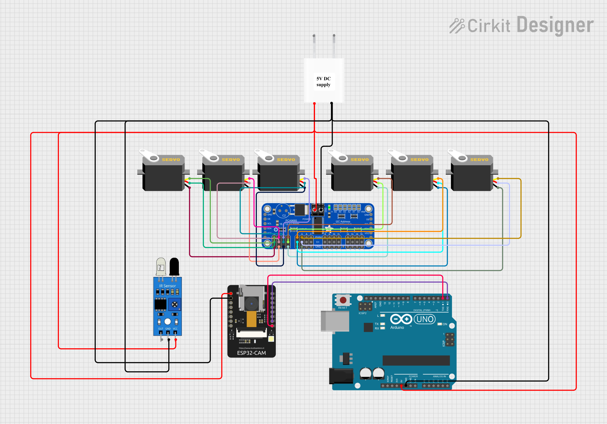
Circuit Documentation
Summary
This circuit is designed to control multiple servo motors using an Adafruit PCA9685 PWM Servo Breakout board, which is interfaced with an Arduino UNO microcontroller. The circuit also includes an ESP32-CAM module for camera functionalities and an IR sensor for detecting infrared signals. A 5V Adapter is used to power the components in the circuit.
Component List
- 5V Adapter: Provides a regulated 5V output from an AC input.
- Servo Motors: Actuators that can be precisely controlled for position.
- Adafruit PCA9685 PWM Servo Breakout: A 16-channel, 12-bit PWM Fm+ I2C-bus LED controller optimized for controlling servo motors.
- ESP32-CAM: A small camera module with the ESP32-S chip that supports Wi-Fi and Bluetooth.
- IR Sensor: Detects infrared signals and can be used for simple remote control systems.
- Arduino UNO: A microcontroller board based on the ATmega328P, widely used for building digital devices and interactive objects.
Wiring Details
5V Adapter
- 5V: Connected to the 5V power rail supplying power to the Adafruit PCA9685, ESP32-CAM, IR sensor, and Arduino UNO.
- GND: Connected to the ground rail, which is common for all components.
Servo Motors
- GND: Connected to the ground rail.
- VCC: Connected to the 5V power rail.
- Pulse: Connected to individual PWM outputs on the Adafruit PCA9685.
Adafruit PCA9685 PWM Servo Breakout
- 5.0V: Connected to the 5V power rail.
- GND: Connected to the ground rail.
- PWRIN: Connected to the 5V power rail.
- PWM Channels (PWM0 to PWM5): Connected to the pulse pins of the respective servo motors.
ESP32-CAM
- 5V: Connected to the 5V power rail.
- GND: Connected to the ground rail.
- VOT: Connected to the TX pin (D1) of the Arduino UNO.
- VOR: Connected to the RX pin (D0) of the Arduino UNO.
IR Sensor
- VCC: Connected to the 5V power rail.
- GND: Connected to the ground rail.
Arduino UNO
- 5V: Connected to the 5V power rail.
- GND: Connected to the ground rail.
- D0: Connected to the VOT pin of the ESP32-CAM.
- D1: Connected to the VOR pin of the ESP32-CAM.
Documented Code
Arduino UNO Code (sketch.ino)
void setup() {
  // put your setup code here, to run once:

}

void loop() {
  // put your main code here, to run repeatedly:

}
Note: The provided code for the Arduino UNO is a template with empty setup and loop functions. The actual implementation should be added to control the Adafruit PCA9685 and communicate with the ESP32-CAM.
Additional Notes
- The ESP32-CAM module requires additional setup and programming to utilize its camera functionalities.
- The Adafruit PCA9685 requires I2C communication setup in the Arduino code to control the PWM outputs for the servo motors.
- The IR sensor's output pin is not connected in the provided net list and would need to be connected to a digital input on the Arduino UNO for use.