
Circuit Documentation
Summary of the Circuit
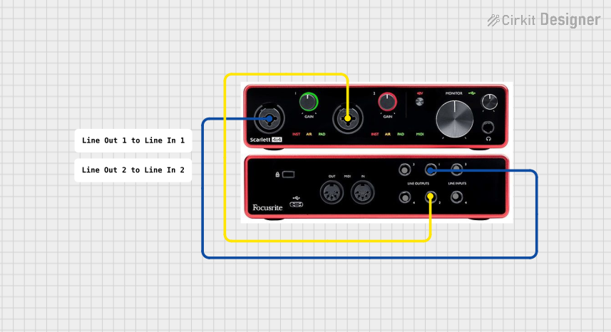
The circuit described in the provided inputs consists of a single audio interface component, the Scarlett 4i4. This device is capable of handling multiple audio inputs and outputs. The circuit's design suggests that it is intended for audio signal routing, with specific connections made between its line inputs and line outputs. There are no other active or passive electronic components listed, and no microcontroller code is provided, indicating that the circuit's functionality is likely managed by the Scarlett 4i4's internal hardware and does not require external control logic.
Component List
Scarlett 4i4
- Description: An audio interface with multiple line inputs and outputs.
- Purpose: To route audio signals within the circuit.
- Pins:
- Line In 1
- Line In 2
- Line In 3
- Line In 4
- Line Out 1
- Line Out 2
- Line Out 3
- Line Out 4
Comment (x2)
- Description: Placeholder components that do not have pins or a specified purpose in the circuit documentation.
Wiring Details
Scarlett 4i4
- Line In 1 is connected to Line Out 1.
- Line In 2 is connected to Line Out 2.
Note: The connections suggest a direct routing from each line input to the corresponding line output. There are no connections listed for Line In 3, Line In 4, Line Out 3, and Line Out 4, which implies that these pins are not used in the current circuit configuration.
Documented Code
No microcontroller code has been provided for this circuit. Therefore, there is no embedded code to document. The Scarlett 4i4 is expected to operate with its internal firmware without the need for additional programming.
This document provides an overview of the circuit based on the provided inputs. For a complete understanding of the circuit's capabilities and operation, refer to the Scarlett 4i4's manufacturer documentation and any additional design notes not included in this summary.