
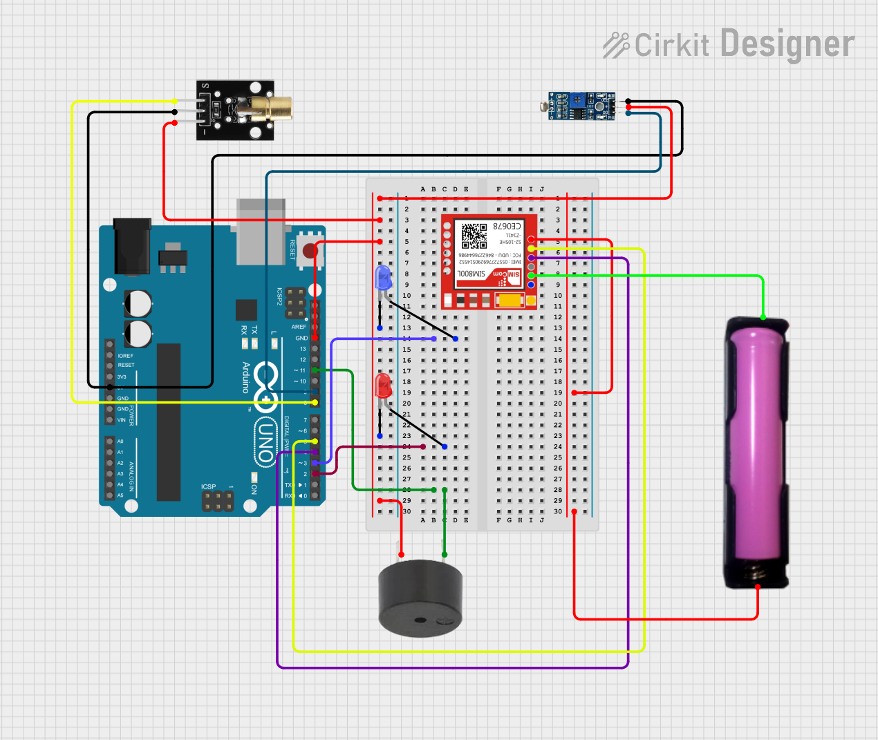
Circuit Documentation
Summary
This circuit is designed to function as a laser tripwire security system. It uses an Arduino UNO microcontroller to control various components including LEDs, a buzzer, a laser emitter, an LDR module, and a SIM800L module for GSM communication. When the laser tripwire is interrupted, the system triggers an alarm and sends a notification via the GSM module.
Component List
KY-008 Laser Emitter
- Pins: SIG, 5V, GND
- Description: Emits a laser beam used as a tripwire.
- Purpose in Circuit: Provides the laser beam for the tripwire.
LED: Two Pin (red)
- Pins: Cathode, Anode
- Description: Red LED.
- Purpose in Circuit: Indicates the status of the tripwire.
LED: Two Pin (blue)
- Pins: Cathode, Anode
- Description: Blue LED.
- Purpose in Circuit: Indicates the status of the tripwire.
Arduino UNO
- Pins: UNUSED, IOREF, Reset, 3.3V, 5V, GND, Vin, A0, A1, A2, A3, A4, A5, SCL, SDA, AREF, D13, D12, D11, D10, D9, D8, D7, D6, D5, D4, D3, D2, D1, D0
- Description: Microcontroller board.
- Purpose in Circuit: Controls all components and processes the logic for the tripwire system.
Buzzer
- Pins: PIN, GND
- Description: Emits sound when activated.
- Purpose in Circuit: Provides an audible alarm when the tripwire is interrupted.
LDR Module 3 pin
- Pins: VCC, GND, DO
- Description: Light-dependent resistor module.
- Purpose in Circuit: Detects the presence of the laser beam.
Sim800l
- Pins: NET, RST, VCC, RXD, TXD, GND
- Description: GSM module.
- Purpose in Circuit: Sends notifications via SMS when the tripwire is interrupted.
18650 in holder
- Pins: GND, VCC
- Description: Battery holder for 18650 battery.
- Purpose in Circuit: Provides power to the GSM module.
Wiring Details
KY-008 Laser Emitter
- SIG connected to D8 on Arduino UNO
- 5V connected to 5V on Arduino UNO
- GND connected to GND on Arduino UNO
LED: Two Pin (red)
- Anode connected to D2 on Arduino UNO
- Cathode connected to GND on LDR Module 3 pin
LED: Two Pin (blue)
- Anode connected to D3 on Arduino UNO
- Cathode connected to GND on LDR Module 3 pin
Arduino UNO
- D2 connected to Anode of red LED
- D3 connected to Anode of blue LED
- D8 connected to SIG of KY-008 Laser Emitter
- D9 connected to DO of LDR Module 3 pin
- D11 connected to PIN of Buzzer
- D4 connected to RXD of Sim800l
- D5 connected to TXD of Sim800l
- 5V connected to 5V of KY-008 Laser Emitter and VCC of LDR Module 3 pin
- GND connected to GND of LDR Module 3 pin, GND of KY-008 Laser Emitter, GND of Buzzer, and GND of Arduino UNO
Buzzer
- PIN connected to D11 on Arduino UNO
- GND connected to GND on Arduino UNO
LDR Module 3 pin
- VCC connected to 5V on Arduino UNO
- GND connected to GND on Arduino UNO
- DO connected to D9 on Arduino UNO
Sim800l
- RXD connected to D4 on Arduino UNO
- TXD connected to D5 on Arduino UNO
- VCC connected to VCC on 18650 in holder
- GND connected to GND on 18650 in holder
18650 in holder
- VCC connected to VCC on Sim800l
- GND connected to GND on Sim800l
Documented Code
#include <SoftwareSerial.h>

//phone number must be with country code
//NOTE: Must be your personal phone number here
//this is not gsm module phone number
const String PHONE = "ENTER_YOUR_PHONE_NUMBER";

//SIM800L Module pin
#define rxPin 4
#define txPin 5
SoftwareSerial sim800L(rxPin,txPin);

#define LASER_RECEIVER_PIN 9
#define LASER_TRANSMIT_PIN 8
//fire_flag = 0 means tripwire detected
boolean laser_flag = 0;

//int Laser = 8;
//int Ldr = 9;
#define BUZZER_PIN 11
//int buzzer = 11;
int led1 = 2;
int led2 = 3;

void setup()
{
    //Begin serial communication: Arduino IDE (Serial Monitor)
    Serial.begin(115200);
    //----------------------------------------------------------------
    //Begin serial communication: SIM800L
    sim800L.begin(9600);
    //----------------------------------------------------------------
    pinMode(LASER_RECEIVER_PIN,INPUT);
    pinMode(LASER_TRANSMIT_PIN,OUTPUT);
    //by default the LASER Transmitter is ON
    digitalWrite(LASER_TRANSMIT_PIN,HIGH);
    //----------------------------------------------------------------
    pinMode(BUZZER_PIN, OUTPUT);
    //by default the BUZZER is OFF
    digitalWrite(BUZZER_PIN,LOW);
    //----------------------------------------------------------------
    //pinMode(Laser,OUTPUT);
    //pinMode(Ldr,INPUT);
    //pinMode(buzzer,OUTPUT);
    pinMode(led1,OUTPUT);
    pinMode(led2,OUTPUT);

    Serial.println("Initializing...");

    //Once the handshake test is successful, it will back to OK
    sim800L.println("AT");
    delay(1000);
    sim800L.println("AT+CMGF=1");
    delay(1000);
    //----------------------------------------------------------------
}

 void loop()
{
    while(sim800L.available())
    {
        Serial.println(sim800L.readString());
    }

    int laser_value = digitalRead(LASER_RECEIVER_PIN);

    if(laser_value == LOW)
    {
        digitalWrite(BUZZER_PIN,HIGH);
        if(laser_flag == 0)
        {
            Serial.println("Laser Tripwire Detected.");
            laser_flag == 1;
            make_call();
        }
        digitalWrite(2,LOW);
        digitalWrite(3,HIGH);
        //----------------------------------------------------------------
    }

    else
    {
        //Serial.println("Laser Tripwire !Detected.");
        digitalWrite(BUZZER_PIN,LOW);
        laser_flag = 0;
        digitalWrite(2,HIGH);
        digitalWrite(3,LOW);
    }

/*
    digitalWrite(8,HIGH);

    if(digitalRead(Ldr)==LOW)
    {
        digitalWrite(11,LOW);
        digitalWrite(2,LOW);
        digitalWrite(3,HIGH);
    }

    else
    {
        digitalWrite(11,HIGH);
        digitalWrite(2,HIGH);
        digitalWrite(3,LOW);
    }
*/
}

void make_call()
{
    Serial.println("calling....");
    sim800L.println("ATD"+PHONE+";");
    delay(20000); //20 sec delay
    sim800L.println("ATH");
    delay(1000); //1 sec delay
}
This code initializes the components and sets up the necessary pin modes. The main loop continuously checks the status of the laser tripwire. If the laser beam is interrupted, the buzzer is activated, and a call is made to the predefined phone number using the SIM800L module. The LEDs indicate the status of the tripwire, with the red LED turning on when the tripwire is intact and the blue LED turning on when the tripwire is interrupted.