Cirkit Designer
Your all-in-one circuit design IDE
Home /
Project Documentation
Arduino-Controlled IR-Activated Dual Relay Light Switch
Circuit Documentation
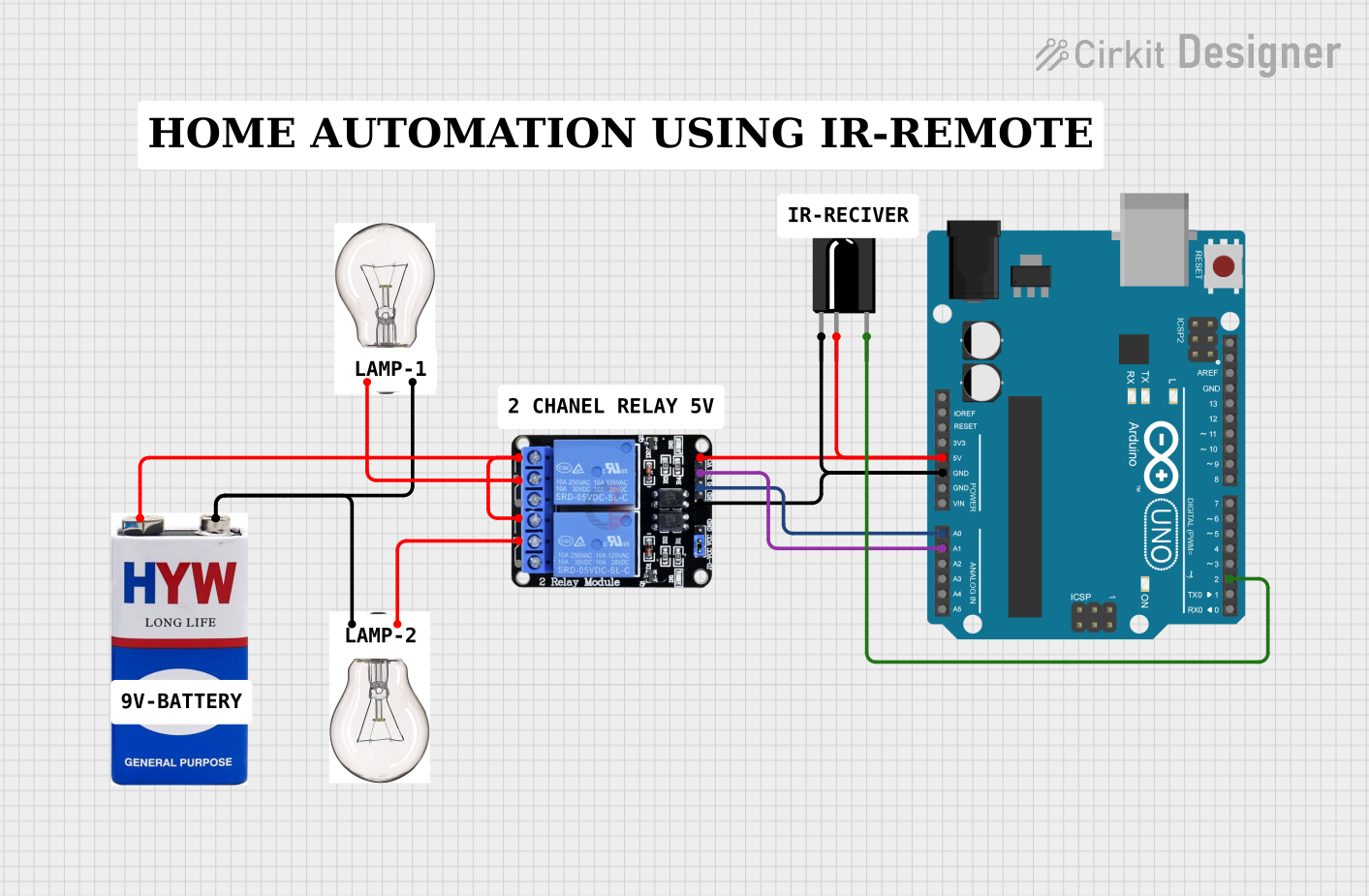
Summary
This circuit integrates an Arduino UNO microcontroller with a TSOP312 IR receiver and a two-channel 5V relay module to control two bulbs. The circuit is powered by a 9V battery. The IR receiver allows the Arduino to receive infrared signals, which can then be used to control the relay module, switching the bulbs on or off. The relay module acts as an electrically operated switch that can handle the high current required by the bulbs, which are powered separately by the 9V battery.
Component List
Arduino UNO
- Description: A microcontroller board based on the ATmega328P.
- Pins: UNUSED, IOREF, Reset, 3.3V, 5V, GND, Vin, A0-A5, SCL, SDA, AREF, D0-D13.
TSOP312 IR Receiver
- Description: An infrared receiver tuned to receive IR signals at 38 kHz.
- Pins: GND, Vs, Data.
Two Channel Relay 5V
- Description: A relay module with two independent relay channels.
- Pins: VCC, IN2, IN1, GND, NC2, C2, NO2, NC1, C1, NO1.
Bulb
- Description: An electric light with two terminals.
- Pins: +VE, _VE.
9V Battery
- Description: A standard 9V battery providing power to the circuit.
- Pins: +, -.
Wiring Details
Arduino UNO
- 5V connected to VCC of the Two Channel Relay 5V and Vs of the TSOP312 IR Receiver.
- GND connected to GND of the Two Channel Relay 5V and GND of the TSOP312 IR Receiver.
- D2 connected to Data of the TSOP312 IR Receiver.
- A0 connected to IN1 of the Two Channel Relay 5V.
- A1 connected to IN2 of the Two Channel Relay 5V.
TSOP312 IR Receiver
- Vs connected to 5V of the Arduino UNO.
- Data connected to D2 of the Arduino UNO.
- GND connected to GND of the Arduino UNO.
Two Channel Relay 5V
- VCC connected to 5V of the Arduino UNO.
- IN1 connected to A0 of the Arduino UNO.
- IN2 connected to A1 of the Arduino UNO.
- GND connected to GND of the Arduino UNO.
- NC1 and NC2 connected to + of the 9V Battery.
- C1 connected to +VE of one bulb.
- C2 connected to +VE of the other bulb.
Bulbs
- +VE of each bulb connected to C1 and C2 of the Two Channel Relay 5V respectively.
- _VE of each bulb connected to - of the 9V Battery.
9V Battery
- + connected to NC1 and NC2 of the Two Channel Relay 5V.
- - connected to _VE of both bulbs.
Documented Code
Arduino UNO Code (sketch.ino)
void setup() {
  // put your setup code here, to run once:

}

void loop() {
  // put your main code here, to run repeatedly:

}
Additional Notes (documentation.txt)
No additional code documentation provided.