
Arduino Nano-Controlled Servo and Sensor Alert System with AC-DC Power Conversion
View and Edit Project In Cirkit Designer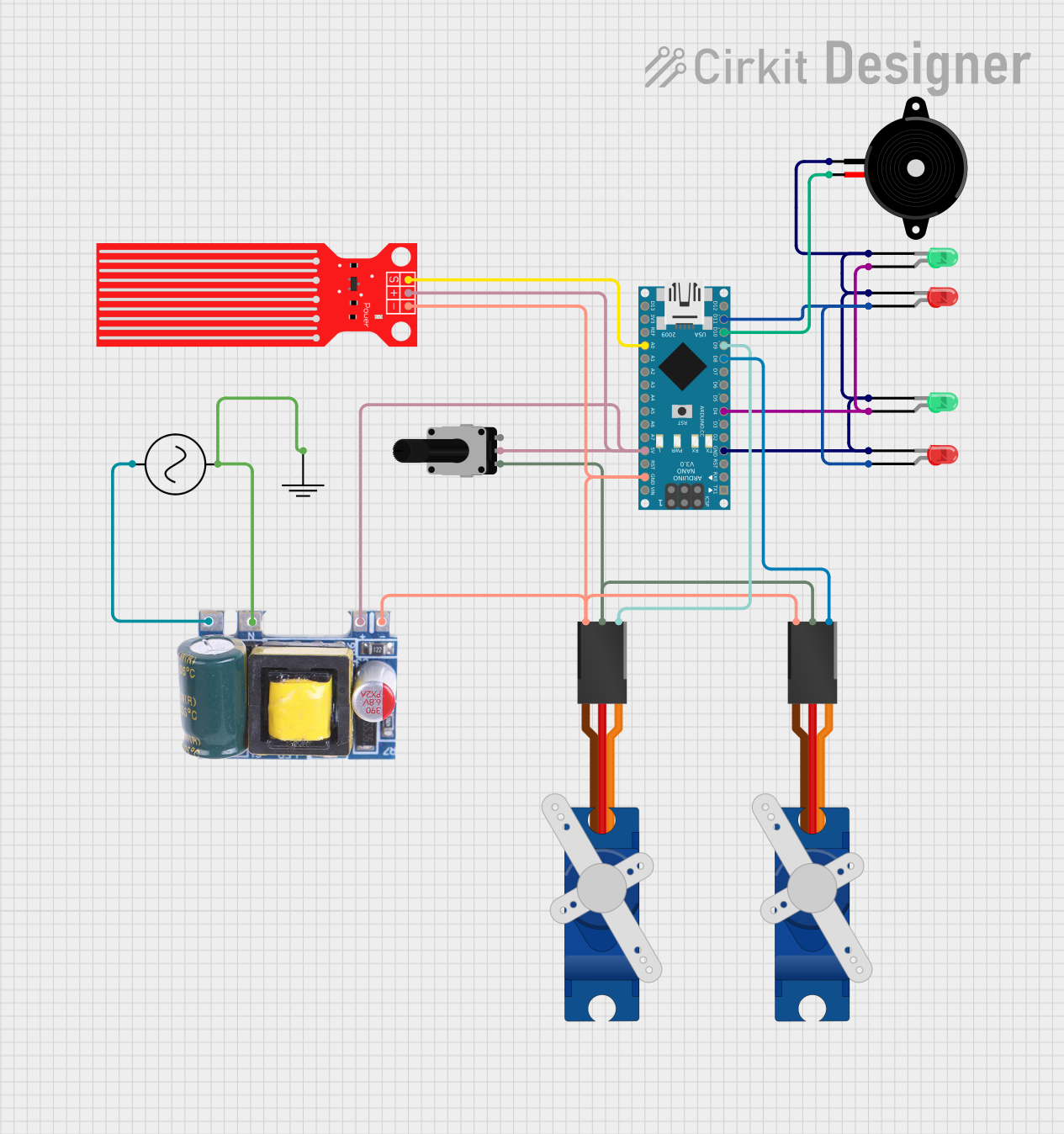
Circuit Documentation
Summary
This document provides a detailed overview of a circuit designed to interface with various components including servos, LEDs, a piezo speaker, a potentiometer, a water level sensor, and an Arduino Nano microcontroller. The circuit is powered by an AC supply connected to a mini AC-DC converter module that steps down the voltage to 5V suitable for the components. The Arduino Nano serves as the central controller, interfacing with the servos, sensors, and output devices to perform specific tasks as dictated by the embedded code.
Component List
Tower Pro SG90 Servo
- Description: A small and lightweight servo motor for precise control of motion.
- Pins: Signal, +5V, GND
Piezo Speaker
- Description: An electronic device that can produce sound when an electrical signal is applied.
- Pins: pin1, pin2
LED: Two Pin (Green)
- Description: A green light-emitting diode used for indication purposes.
- Pins: cathode, anode
LED: Two Pin (Red)
- Description: A red light-emitting diode used for indication purposes.
- Pins: cathode, anode
Rotary Potentiometer
- Description: A variable resistor with a knob used to provide analog input.
- Pins: leg1, wiper, leg2
- Properties: Resistance: 10000 Ohms
Water Level Sensor
- Description: A sensor used to detect the level of water in a container.
- Pins: SIG, VCC, GND
Arduino Nano
- Description: A compact microcontroller board based on the ATmega328P.
- Pins: D1/TX, D0/RX, RESET, GND, D2, D3, D4, D5, D6, D7, D8, D9, D10, D11/MOSI, D12/MISO, VIN, 5V, A7, A6, A5, A4, A3, A2, A1, A0, AREF, 3V3, D13/SCK
AC Supply
- Description: The main power source for the circuit.
- Pins: +ve, -ve
Mini AC-DC 110V-230V to 5V 700mA Module
- Description: A power supply module that converts AC voltage to 5V DC.
- Pins: GND, 5v, Neutral, Life
GND
- Description: A common ground reference point for the circuit.
- Pins: GND
Wiring Details
Tower Pro SG90 Servo
- Signal: Connected to Arduino Nano D9 (for one servo) and D8 (for the other servo).
- +5V: Connected to the +5V net, which includes the Rotary Potentiometer leg1 and the other servo's +5V.
- GND: Connected to the common ground net.
Piezo Speaker
- pin1: Connected to the common ground net.
- pin2: Connected to Arduino Nano D10.
LED: Two Pin (Green)
- cathode: Connected to the common ground net.
- anode: Connected to Arduino Nano D4.
LED: Two Pin (Red)
- cathode: Connected to the common ground net.
- anode: Connected to Arduino Nano D11/MOSI.
Rotary Potentiometer
- leg1: Connected to the +5V net.
- wiper: Connected to Arduino Nano 5V.
- leg2: Not connected in the provided net list.
Water Level Sensor
- SIG: Connected to Arduino Nano A0.
- VCC: Connected to the +5V net.
- GND: Connected to the common ground net.
Arduino Nano
- D9, D8: Connected to the servos' signal pins.
- D10: Connected to the Piezo Speaker pin2.
- D4: Connected to the anodes of the green LEDs.
- D11/MOSI: Connected to the anodes of the red LEDs.
- 5V: Connected to the +5V net.
- GND: Connected to the common ground net.
- A0: Connected to the Water Level Sensor SIG.
AC Supply
- +ve: Connected to the Mini AC-DC Module Life.
- -ve: Connected to the common ground net.
Mini AC-DC 110V-230V to 5V 700mA Module
- GND: Connected to the common ground net.
- 5v: Connected to the +5V net.
- Neutral: Connected to the common ground net.
- Life: Connected to the AC Supply +ve.
GND
- GND: Acts as the common ground reference for the entire circuit.
Documented Code
Arduino Nano - sketch.ino
void setup() {
  // put your setup code here, to run once:

}

void loop() {
  // put your main code here, to run repeatedly:

}
Arduino Nano - documentation.txt
(No additional documentation provided for the code)
This concludes the documentation for the provided circuit. The code provided for the Arduino Nano is a template and does not contain any functional instructions. Further implementation is required to control the components as per the circuit's intended use.