Cirkit Designer
Your all-in-one circuit design IDE
Home /
Project Documentation
Arduino Mega 2560 Smart Irrigation System with Rain/Snow Sensor and Battery-Powered Water Pump
Circuit Documentation
Summary
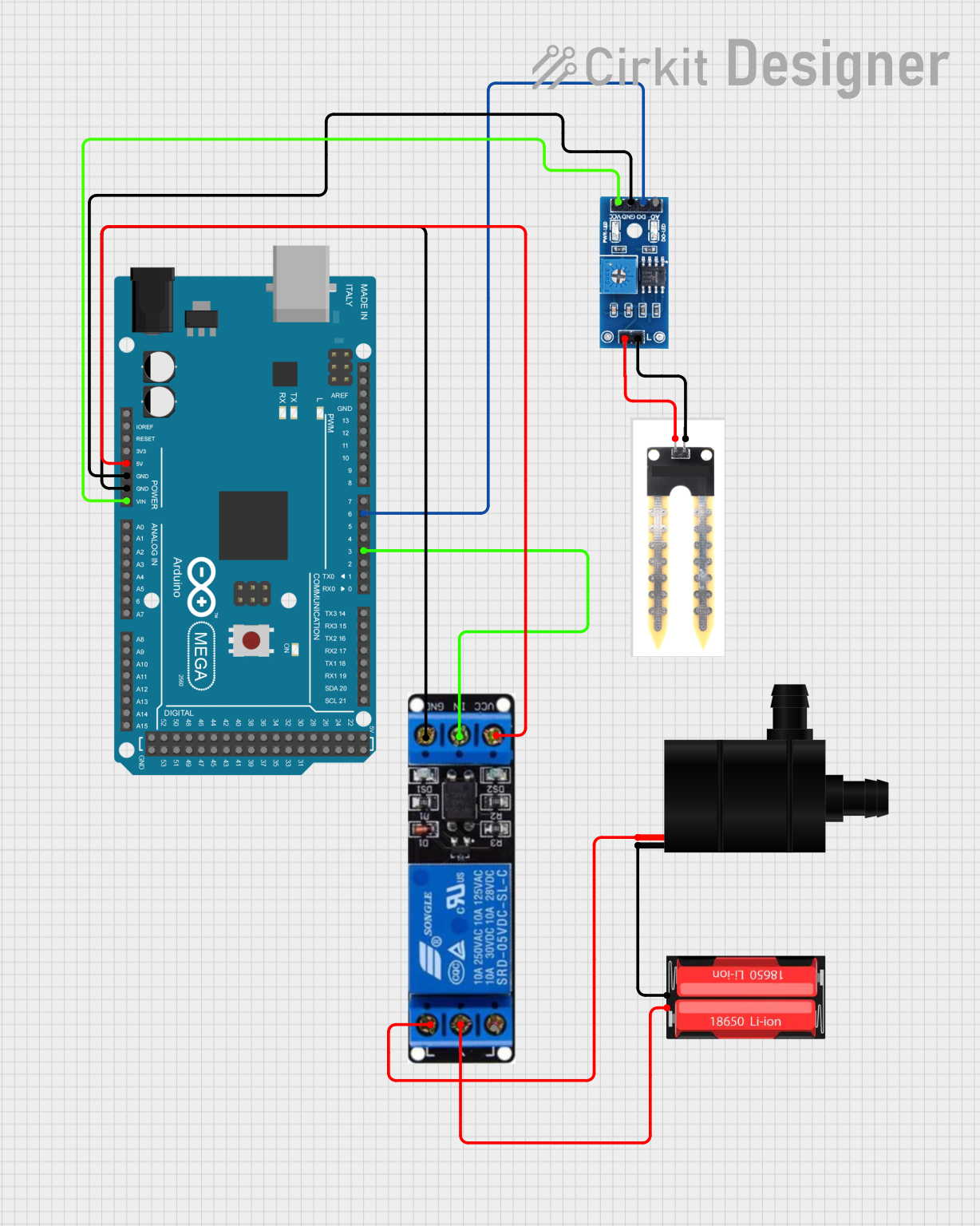
This circuit is designed to control a water pump based on the readings from a soil moisture sensor and a rain/snow sensor. The system uses an Arduino Mega 2560 microcontroller to read sensor data and control a relay, which in turn controls the water pump. The circuit is powered by a 18650 Li-Ion battery.
Component List
Water Pump
- Pins: VCC, GND
- Description: A pump used to move water.
- Purpose in Circuit: To provide water based on sensor readings.
Arduino Mega 2560
- Pins: IOREF, RESET, 3V3, 5V, GND, VIN, A0-A15, D0-D53, AREF, SDA, SCL
- Description: A microcontroller board based on the ATmega2560.
- Purpose in Circuit: To read sensor data and control the relay.
Rain/Snow Sensor - Board
- Pins: 1, 2, A0 (Analog), D0 (Digital), GND, VCC (5V)
- Description: A sensor to detect rain or snow.
- Purpose in Circuit: To provide environmental data to the microcontroller.
18650 Li-Ion
- Pins: Positive, Negative
- Description: A rechargeable lithium-ion battery.
- Purpose in Circuit: To power the water pump and relay.
Soil Moisture Sensor
- Pins: Positive, Negative
- Description: A sensor to measure soil moisture levels.
- Purpose in Circuit: To provide soil moisture data to the microcontroller.
Relay 12V
- Pins: Ground, In, VCC, NO, COM, NC
- Description: A relay module to control high-power devices.
- Purpose in Circuit: To control the water pump based on microcontroller signals.
Wiring Details
Water Pump
- VCC connected to NO of Relay 12V
- GND connected to Negative of 18650 Li-Ion
Arduino Mega 2560
- 5V connected to VCC of Relay 12V
- GND connected to GND of Rain/Snow Sensor - Board
- GND connected to Ground of Relay 12V
- VIN connected to VCC (5V) of Rain/Snow Sensor - Board
- D3 PWM connected to In of Relay 12V
- D6 PWM connected to D0 (Digital) of Rain/Snow Sensor - Board
Rain/Snow Sensor - Board
- GND connected to GND of Arduino Mega 2560
- VCC (5V) connected to VIN of Arduino Mega 2560
- D0 (Digital) connected to D6 PWM of Arduino Mega 2560
- 1 connected to Negative of Soil Moisture Sensor
- 2 connected to Positive of Soil Moisture Sensor
18650 Li-Ion
- Negative connected to GND of Water Pump
- Positive connected to COM of Relay 12V
Soil Moisture Sensor
- Negative connected to 1 of Rain/Snow Sensor - Board
- Positive connected to 2 of Rain/Snow Sensor - Board
Relay 12V
- Ground connected to GND of Arduino Mega 2560
- In connected to D3 PWM of Arduino Mega 2560
- VCC connected to 5V of Arduino Mega 2560
- NO connected to VCC of Water Pump
- COM connected to Positive of 18650 Li-Ion
Documented Code
Arduino Mega 2560 Code
int water; //random variable

void setup() {
  pinMode(3, OUTPUT); //output pin for relay board, this will send signal to the relay
  pinMode(6, INPUT); //input pin coming from soil sensor
}

void loop() {
  water = digitalRead(6);  // reading the coming signal from the soil sensor
  if (water == HIGH) { // if water level is full then cut the relay
    digitalWrite(3, LOW); // low is to cut the relay
  } else {
    digitalWrite(3, HIGH); //high to continue providing signal and water supply
  }
  delay(400);
}
This code initializes the pins for the relay and soil sensor, reads the soil moisture level, and controls the relay to turn the water pump on or off based on the moisture level.