
Arduino UNO-Based Fire Detection System with GSM Alert and LCD Display
View and Edit Project In Cirkit Designer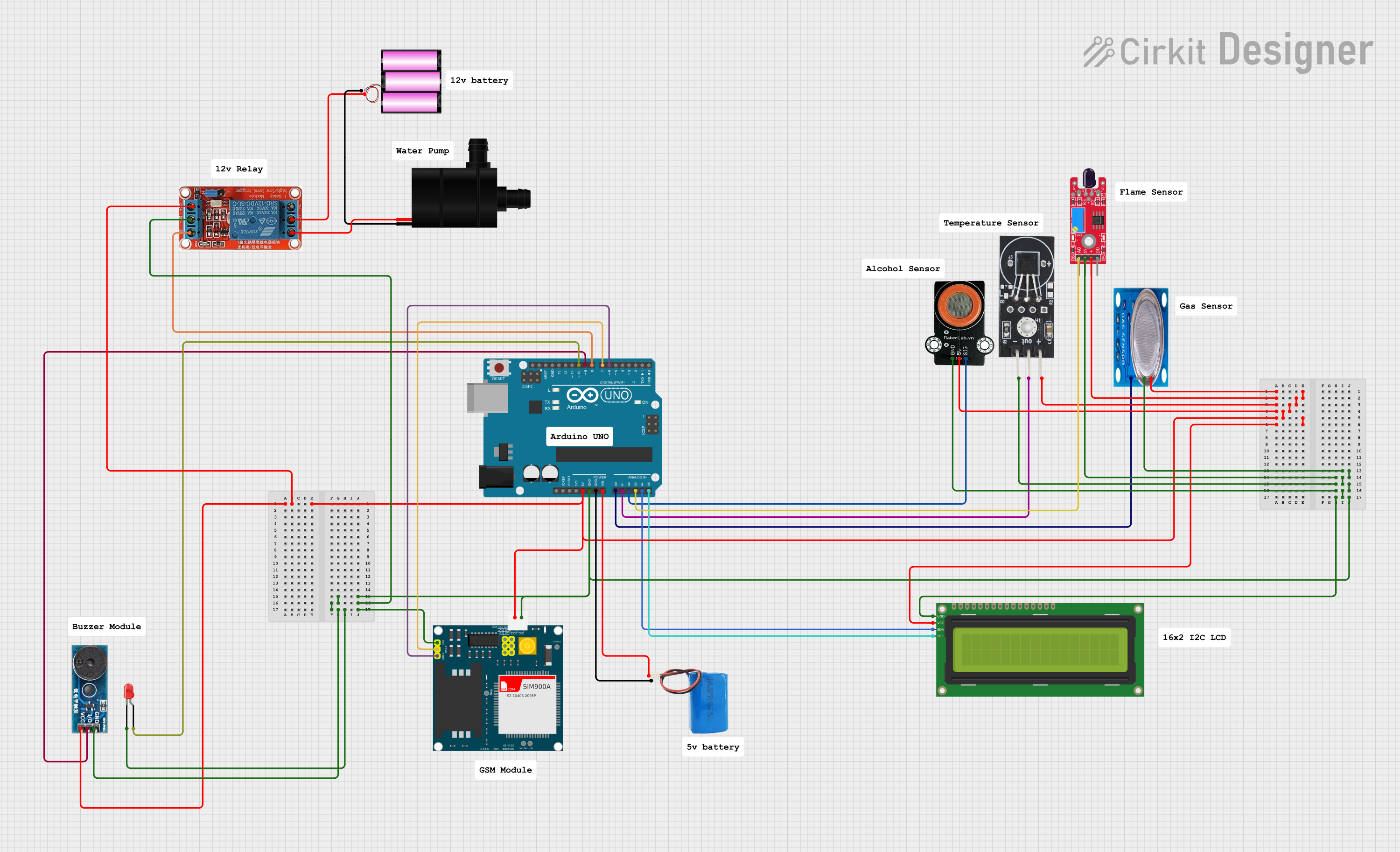
Circuit Documentation
Summary
This circuit is a fire detection and alert system. It utilizes various sensors to detect fire, gas, and temperature anomalies. When a hazard is detected, the system activates a water pump, a buzzer, and an LED indicator. Additionally, it sends an SMS alert using a GSM module. The system is controlled by an Arduino UNO microcontroller, and it displays status information on a 16x2 I2C LCD.
Component List
KY-026 Flame Sensor
- Pins: AO, GND, VCC, DO
- Description: Detects the presence of flame or fire.
- Purpose in Circuit: Provides analog output to indicate flame intensity.
DS18B20 Temperature Sensor
- Pins: GND, VCC, OUT
- Description: Measures temperature.
- Purpose in Circuit: Provides temperature readings to the microcontroller.
MKE-S07 MQ-3 Alcohol Sensor
- Pins: GND, 5V, SIG
- Description: Detects alcohol concentration in the air.
- Purpose in Circuit: Provides analog output to indicate alcohol levels.
Buzzer Module
- Pins: GND, Vcc, I/O
- Description: Emits sound when activated.
- Purpose in Circuit: Alerts users when a hazard is detected.
LED: Two Pin (red)
- Pins: Cathode, Anode
- Description: Emits light when activated.
- Purpose in Circuit: Visual indicator for hazard detection.
Water Pump
- Pins: VCC, GND
- Description: Pumps water when activated.
- Purpose in Circuit: Extinguishes fire when a hazard is detected.
16x2 I2C LCD
- Pins: GND, VCC, SDA, SCL
- Description: Displays information.
- Purpose in Circuit: Shows system status and sensor readings.
Arduino UNO
- Pins: UNUSED, IOREF, Reset, 3.3V, 5V, GND, Vin, A0, A1, A2, A3, A4, A5, SCL, SDA, AREF, D13, D12, D11, D10, D9, D8, D7, D6, D5, D4, D3, D2, D1, D0
- Description: Microcontroller.
- Purpose in Circuit: Controls the entire system.
MQ-5 Gas Sensor
- Pins: VCC, GND, Digi Out, Analog out
- Description: Detects gas concentration in the air.
- Purpose in Circuit: Provides analog output to indicate gas levels.
12v Relay
- Pins: NO, COM, NC, IN, DC-, DC+
- Description: Switches high-power devices.
- Purpose in Circuit: Controls the water pump.
SIM900A GSM Module
- Pins: GND, DB9-3 (RXD), DB9-2 (TXD), 5V, 3VR, 5VR, 3VT, 5VT, VCC, Ring, RESTART, RESET, STATUS
- Description: Sends SMS alerts.
- Purpose in Circuit: Sends SMS when a hazard is detected.
5v Battery
- Pins: Positive, Negative
- Description: Provides 5V power supply.
- Purpose in Circuit: Powers the Arduino UNO and other 5V components.
12v Battery
- Pins: +, -
- Description: Provides 12V power supply.
- Purpose in Circuit: Powers the water pump and relay.
Wiring Details
KY-026 Flame Sensor
- VCC to 5V net
- GND to GND net
- AO to Arduino UNO A3
DS18B20 Temperature Sensor
- VCC to 5V net
- GND to GND net
- OUT to Arduino UNO A1
MKE-S07 MQ-3 Alcohol Sensor
- 5V to 5V net
- GND to GND net
- SIG to Arduino UNO A2
Buzzer Module
- Vcc to 5V net
- GND to GND net
- I/O to Arduino UNO D9
LED: Two Pin (red)
- Anode to Arduino UNO D10
- Cathode to GND net
Water Pump
- VCC to 12v Relay NO
- GND to 12v Battery -
16x2 I2C LCD
- VCC to 5V net
- GND to GND net
- SDA to Arduino UNO A4
- SCL to Arduino UNO A5
Arduino UNO
- 5V to 5V net
- GND to GND net
- Vin to 5v Battery Positive
- A0 to MQ-5 Analog out
- A1 to DS18B20 OUT
- A2 to MKE-S07 MQ-3 SIG
- A3 to KY-026 AO
- D6 to SIM900A DB9-2 (TXD)
- D7 to SIM900A DB9-3 (RXD)
- D8 to 12v Relay IN
- D9 to Buzzer Module I/O
- D10 to LED Anode
MQ-5 Gas Sensor
- VCC to 5V net
- GND to GND net
- Analog out to Arduino UNO A0
12v Relay
- DC+ to 5V net
- DC- to GND net
- IN to Arduino UNO D8
- NO to Water Pump VCC
- COM to 12v Battery +
SIM900A GSM Module
- 5V to 5V net
- GND to GND net
- DB9-2 (TXD) to Arduino UNO D6
- DB9-3 (RXD) to Arduino UNO D7
5v Battery
- Positive to Arduino UNO Vin
- Negative to GND net
12v Battery
- + to 12v Relay COM
- - to Water Pump GND
Code Documentation
#include <Wire.h>
#include <LiquidCrystal_I2C.h>
#include <SoftwareSerial.h>
#include <OneWire.h>
#include <DallasTemperature.h>

// Pin definitions
const int flameSensorPin = A3;
const int gasSensorPin = A0;
const int tempSensorPin = A1;
const int smokeSensorPin = A2;
const int waterPumpPin = 8;
const int buzzerPin = 9;
const int ledPin = 10;

// GSM module pins
SoftwareSerial gsm(6, 7); // RX, TX

// Temperature sensor setup
OneWire oneWire(tempSensorPin);
DallasTemperature sensors(&oneWire);

// LCD setup
LiquidCrystal_I2C lcd(0x27, 16, 2);

void setup() {
  Serial.begin(9600);
  gsm.begin(9600);
  sensors.begin();
  lcd.begin(0x27, 16, 2);
  lcd.backlight();

  pinMode(waterPumpPin, OUTPUT);
  pinMode(buzzerPin, OUTPUT);
  pinMode(ledPin, OUTPUT);
  pinMode(flameSensorPin, INPUT);
  pinMode(gasSensorPin, INPUT);
  pinMode(smokeSensorPin, INPUT);

  lcd.setCursor(0, 0);
  lcd.print("Fire Detection");
  lcd.setCursor(0, 1);
  lcd.print("System Ready");
  delay(2000);
  lcd.clear();
}

void loop() {
  sensors.requestTemperatures();
  float temperature = sensors.getTempCByIndex(0);
  int flameValue = analogRead(flameSensorPin);
  int gasValue = analogRead(gasSensorPin);
  int smokeValue = analogRead(smokeSensorPin);

  lcd.setCursor(0, 0);
  lcd.print("Temp: ");
  lcd.print(temperature);
  lcd.print("C");

  lcd.setCursor(0, 1);
  lcd.print("Flame: ");
  lcd.print(flameValue);

  lcd.print(" Gas: ");
  lcd.print(gasValue);

  lcd.print(" Smoke: ");
  lcd.print(smokeValue);

  if (flameValue > 500 || gasValue > 300 || smokeValue > 300 || temperature > 50) {
    digitalWrite(waterPumpPin, HIGH);
    digitalWrite(buzzerPin, HIGH);
    digitalWrite(ledPin, HIGH);
    sendSMS();
  } else {
    digitalWrite(waterPumpPin, LOW);
    digitalWrite(buzzerPin, LOW);
    digitalWrite(ledPin, LOW