
Arduino UNO-Based RS485 Communication System with Potentiometer-Controlled LEDs
View and Edit Project In Cirkit Designer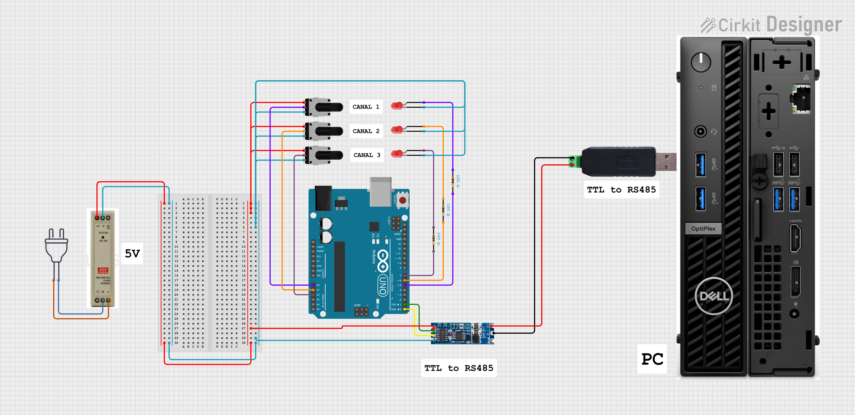
Circuit Documentation
Summary
This circuit involves an Arduino UNO microcontroller interfacing with multiple components including rotary potentiometers, LEDs, resistors, a UART TTL to RS485 converter, an RS485 to USB converter, and a 5V power supply unit (PSU). The circuit is designed to read analog inputs from potentiometers, control LEDs, and facilitate communication between the Arduino and a computer via RS485 and USB.
Component List
Arduino UNO
- Description: Microcontroller board based on the ATmega328P.
- Pins: UNUSED, IOREF, Reset, 3.3V, 5V, GND, Vin, A0, A1, A2, A3, A4, A5, SCL, SDA, AREF, D13, D12, D11, D10, D9, D8, D7, D6, D5, D4, D3, D2, D1, D0
UART TTL to RS485 Two-way Converter
- Description: Converts UART TTL signals to RS485 signals.
- Pins: VCC, TXD, RXD, GND, A, B
RS485 to USB Converter
- Description: Converts RS485 signals to USB signals.
- Pins: A/TX, B/RX
5V PSU
- Description: 5V power supply unit.
- Pins: 5V+, GND, 5V OK, PE, N, L
Power 220V
- Description: 220V AC power source.
- Pins: hot wire, neutral wire
Rotary Potentiometer
- Description: Variable resistor with a resistance of 10k Ohms.
- Pins: leg1, wiper, leg2
LED: Two Pin (red)
- Description: Red LED.
- Pins: cathode, anode
Resistor
- Description: Fixed resistor with a resistance of 100 Ohms.
- Pins: pin1, pin2
Wiring Details
Arduino UNO
- A0 connected to wiper of Rotary Potentiometer
- A1 connected to wiper of Rotary Potentiometer
- A2 connected to wiper of Rotary Potentiometer
- D7 connected to pin2 of Resistor
- D6 connected to pin2 of Resistor
- D5 connected to pin2 of Resistor
- D1 connected to TXD of UART TTL to RS485 Two-way Converter
- D0 connected to RXD of UART TTL to RS485 Two-way Converter
UART TTL to RS485 Two-way Converter
- VCC connected to leg1 of Rotary Potentiometer
- VCC connected to leg1 of Rotary Potentiometer
- VCC connected to leg1 of Rotary Potentiometer
- VCC connected to 5V+ of 5V PSU
- GND connected to leg2 of Rotary Potentiometer
- GND connected to leg2 of Rotary Potentiometer
- GND connected to leg2 of Rotary Potentiometer
- GND connected to cathode of LED: Two Pin (red)
- GND connected to cathode of LED: Two Pin (red)
- GND connected to cathode of LED: Two Pin (red)
- GND connected to GND of 5V PSU
- A connected to A/TX of RS485 to USB Converter
- B connected to B/RX of RS485 to USB Converter
RS485 to USB Converter
- A/TX connected to A of UART TTL to RS485 Two-way Converter
- B/RX connected to B of UART TTL to RS485 Two-way Converter
5V PSU
- 5V+ connected to VCC of UART TTL to RS485 Two-way Converter
- GND connected to GND of UART TTL to RS485 Two-way Converter
- N connected to neutral wire of Power 220V
- L connected to hot wire of Power 220V
Power 220V
- neutral wire connected to N of 5V PSU
- hot wire connected to L of 5V PSU
Rotary Potentiometer
- leg1 connected to VCC of UART TTL to RS485 Two-way Converter
- leg2 connected to GND of UART TTL to RS485 Two-way Converter
- wiper connected to A0 of Arduino UNO
Rotary Potentiometer
- leg1 connected to VCC of UART TTL to RS485 Two-way Converter
- leg2 connected to GND of UART TTL to RS485 Two-way Converter
- wiper connected to A1 of Arduino UNO
Rotary Potentiometer
- leg1 connected to VCC of UART TTL to RS485 Two-way Converter
- leg2 connected to GND of UART TTL to RS485 Two-way Converter
- wiper connected to A2 of Arduino UNO
LED: Two Pin (red)
- cathode connected to GND of UART TTL to RS485 Two-way Converter
- anode connected to pin1 of Resistor
LED: Two Pin (red)
- cathode connected to GND of UART TTL to RS485 Two-way Converter
- anode connected to pin1 of Resistor
LED: Two Pin (red)
- cathode connected to GND of UART TTL to RS485 Two-way Converter
- anode connected to pin1 of Resistor
Resistor
- pin1 connected to anode of LED: Two Pin (red)
- pin2 connected to D7 of Arduino UNO
Resistor
- pin1 connected to anode of LED: Two Pin (red)
- pin2 connected to D6 of Arduino UNO
Resistor
- pin1 connected to anode of LED: Two Pin (red)
- pin2 connected to D5 of Arduino UNO
Documented Code
Arduino UNO Code (sketch.ino)
void setup() {
  // put your setup code here, to run once:

}

void loop() {
  // put your main code here, to run repeatedly:

}
Documentation (documentation.txt)
This documentation provides a comprehensive overview of the circuit, including a summary, detailed component list, wiring details, and the code used in the microcontroller.