
Circuit Documentation
Summary of the Circuit
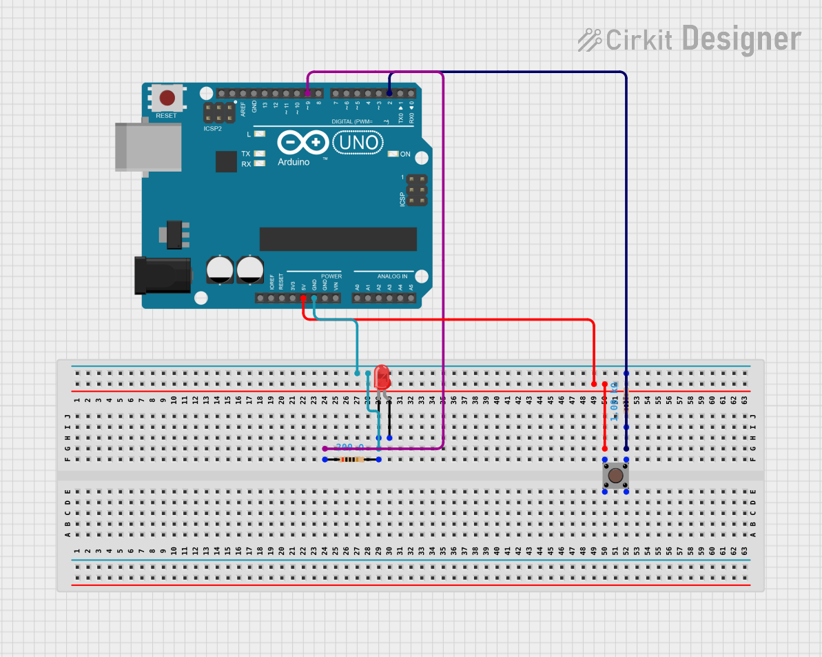
This circuit is designed to control an LED using an Arduino UNO microcontroller in response to the state of a pushbutton. When the button is pressed, the LED turns off; when the button is not pressed, the LED remains on. The circuit includes two resistors, one to limit the current to the LED and another as a pull-down for the pushbutton. The Arduino UNO is programmed to read the state of the pushbutton and control the LED accordingly.
Component List
Resistor (1 kOhms)
- Description: A resistor with a resistance of 1 kOhms.
- Purpose: To limit the current flowing through the LED.
Resistor (200 Ohms)
- Description: A resistor with a resistance of 200 Ohms.
- Purpose: To serve as a pull-down resistor for the pushbutton.
LED: Two Pin (red)
- Description: A standard red LED with an anode and cathode.
- Purpose: To provide a visual indication when powered.
Pushbutton
- Description: A simple pushbutton with four pins.
- Purpose: To allow the user to interact with the circuit, controlling the LED state.
Arduino UNO
- Description: A microcontroller board based on the ATmega328P.
- Purpose: To control the LED based on the pushbutton's state and to provide power to the circuit.
Wiring Details
Resistor (1 kOhms)
- Connected to:
- One end to the cathode of the LED.
- The other end to the ground (GND) of the Arduino UNO.
Resistor (200 Ohms)
- Connected to:
- One end to the digital pin D9 of the Arduino UNO.
- The other end to the cathode of the LED and the 1 kOhms resistor.
LED: Two Pin (red)
- Anode: Connected to the digital pin D9 of the Arduino UNO through a 200 Ohms resistor.
- Cathode: Connected to the ground (GND) of the Arduino UNO through a 1 kOhms resistor.
Pushbutton
- Pin 1 (in): Connected to the 5V of the Arduino UNO.
- Pin 3 (out): Connected to the digital pin D2 of the Arduino UNO and the 1 kOhms resistor.
Arduino UNO
- 5V: Provides power to the pushbutton.
- GND: Common ground for the LED and the 1 kOhms resistor.
- D9: Controls the LED through a 200 Ohms resistor.
- D2: Reads the state of the pushbutton.
Documented Code
// Code for controlling an LED with a pushbutton using Arduino UNO
const int LED = 9;      // LED connected to digital pin 9
const int BUTTON = 2;   // Pushbutton connected to digital pin 2

void setup() {
  pinMode(LED, OUTPUT);    // Set the LED pin as an output
  pinMode(BUTTON, INPUT);  // Set the pushbutton pin as an input
}

void loop() {
  // Read the state of the pushbutton
  if (digitalRead(BUTTON) == LOW) {
    // If the button is pressed, turn off the LED
    digitalWrite(LED, LOW);
  } else {
    // If the button is not pressed, turn on the LED
    digitalWrite(LED, HIGH);
  }
}
- File Name: sketch.ino
- Description: This Arduino sketch sets up pin modes for the LED and pushbutton. In the main loop, it reads the state of the pushbutton. If the button is pressed (logic LOW), the LED is turned off. Otherwise, the LED is turned on.