
Battery-Powered Arduino UNO and ESP-8266 Smart Controller with LCD and RTC
View and Edit Project In Cirkit Designer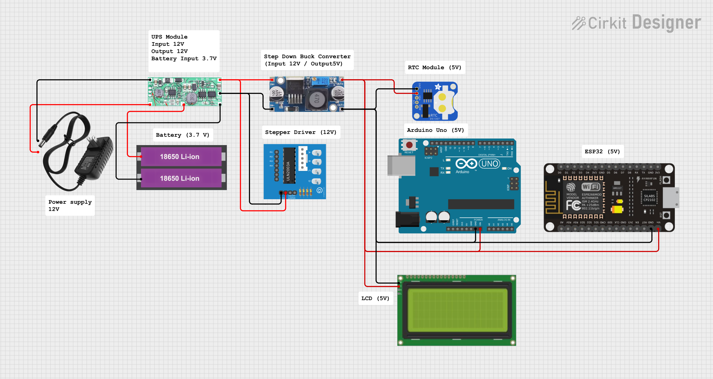
Circuit Documentation
Summary
This document provides a detailed overview of a circuit that includes various components such as a ULN2003A breakout board, a Module UPS Voltage, a Step down Buck converter, a DS1307 RTC, an Arduino UNO, an ESP-8266 Controller, an LCD 20x4 I2C display, and a 12V power supply. The circuit is designed to manage power distribution and control various peripherals using the Arduino UNO and ESP-8266 microcontrollers.
Component List
ULN2003A Breakout Board
- Description: A Darlington transistor array used for driving high-current loads.
- Pins: In 1, In 2, In 3, In 4, In 5, In 6, In 7, 0V, +5V, ON/OFF jumper switch, BLUE wire, PINK wire, YELLOW wire, ORANGE wire, RED wire
Module UPS Voltage
- Description: A UPS module for providing uninterrupted power supply.
- Pins: Input DC + 5V-12V, INPUT DC - 0V, Output + Load Positive, Battery 0V Negative, Battery + 3.7V~4.2V Positive
Step Down Buck Converter
- Description: A DC-DC converter that steps down voltage.
- Pins: IN +, IN - GND, OUT +, OUT - GND
DS1307 RTC (Wokwi Compatible)
- Description: A real-time clock module.
- Pins: GND, 5V, SDA, SCL, SQW
Arduino UNO
- Description: A microcontroller board based on the ATmega328P.
- Pins: UNUSED, IOREF, Reset, 3.3V, 5V, GND, Vin, A0, A1, A2, A3, A4, A5, SCL, SDA, AREF, D13, D12, D11, D10, D9, D8, D7, D6, D5, D4, D3, D2, D1, D0
ESP-8266 Controller
- Description: A Wi-Fi microcontroller module.
- Pins: A0, RSV, SD3, SD5, SD1, CMD, D0, D1, D2, D3, D4, 3V3, GND, D5, D6, SD0, CLK, RST, EN, D7, D8, RX, TX, Vin, 5V
LCD 20x4 I2C
- Description: A 20x4 character LCD display with I2C interface.
- Pins: GND, 5v, SCA, SCL
18650 Li-ion Battery x 2
- Description: Two 18650 Li-ion batteries for power supply.
- Pins: +, -
12V Power Supply
- Description: A 12V DC power supply.
- Pins: +, -
Wiring Details
ULN2003A Breakout Board
- 0V: Connected to Module UPS Voltage and Step Down Buck Converter (IN - GND)
- +5V: Connected to Module UPS Voltage (Output + Load Positive) and Step Down Buck Converter (IN +)
Module UPS Voltage
- Input DC + 5V-12V: Connected to 12V Power Supply (+)
- INPUT DC - 0V: Connected to 12V Power Supply (-)
- Output + Load Positive: Connected to ULN2003A Breakout Board (+5V) and Step Down Buck Converter (IN +)
- Battery 0V Negative: Connected to 18650 Li-ion Battery x 2 (-)
- Battery + 3.7V~4.2V Positive: Connected to 18650 Li-ion Battery x 2 (+)
Step Down Buck Converter
- IN +: Connected to Module UPS Voltage (Output + Load Positive) and ULN2003A Breakout Board (+5V)
- IN - GND: Connected to Module UPS Voltage and ULN2003A Breakout Board (0V)
- OUT +: Connected to DS1307 RTC (5V), LCD 20x4 I2C (5v), ESP-8266 Controller (Vin), and Arduino UNO (Vin)
- OUT - GND: Connected to DS1307 RTC (GND), LCD 20x4 I2C (GND), ESP-8266 Controller (GND), and Arduino UNO (GND)
DS1307 RTC (Wokwi Compatible)
- 5V: Connected to Step Down Buck Converter (OUT +)
- GND: Connected to Step Down Buck Converter (OUT - GND)
Arduino UNO
- Vin: Connected to Step Down Buck Converter (OUT +)
- GND: Connected to Step Down Buck Converter (OUT - GND)
ESP-8266 Controller
- Vin: Connected to Step Down Buck Converter (OUT +)
- GND: Connected to Step Down Buck Converter (OUT - GND)
LCD 20x4 I2C
- 5v: Connected to Step Down Buck Converter (OUT +)
- GND: Connected to Step Down Buck Converter (OUT - GND)
18650 Li-ion Battery x 2
- +: Connected to Module UPS Voltage (Battery + 3.7V~4.2V Positive)
- -: Connected to Module UPS Voltage (Battery 0V Negative)
12V Power Supply
- +: Connected to Module UPS Voltage (Input DC + 5V-12V)
- -: Connected to Module UPS Voltage (INPUT DC - 0V)
Documented Code
Arduino UNO Code (sketch.ino)
void setup() {
  // put your setup code here, to run once:

}

void loop() {
  // put your main code here, to run repeatedly:

}
Additional Documentation (documentation.txt)