Cirkit Designer
Your all-in-one circuit design IDE
Home /
Project Documentation
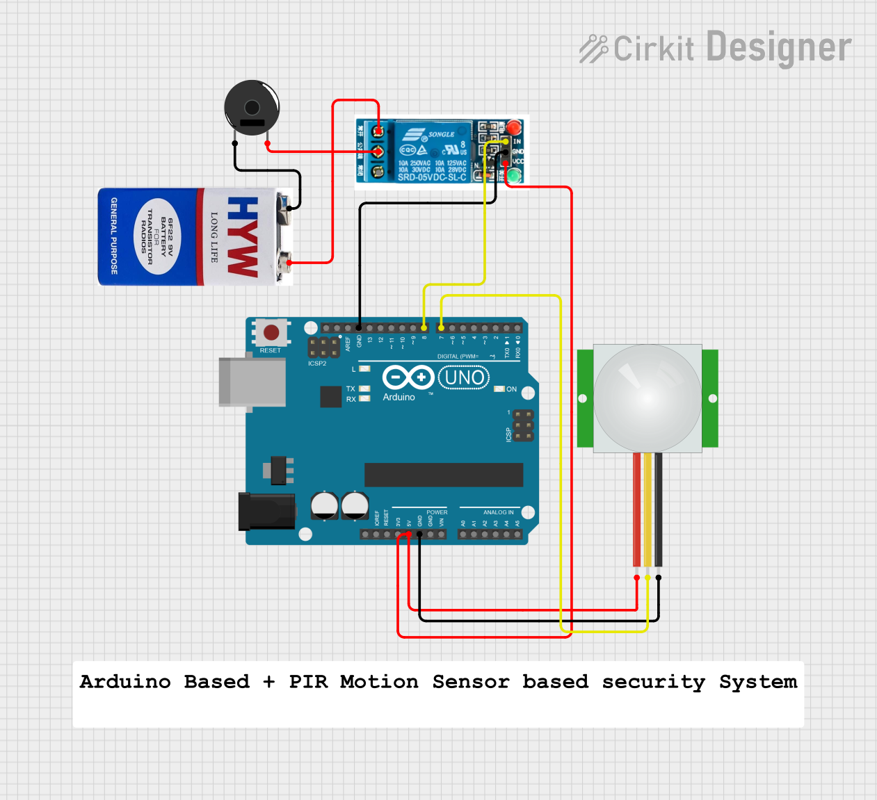
Arduino UNO Motion-Activated Alarm System with PIR Sensor and Piezo Buzzer
Circuit Documentation
Summary
This circuit is designed to interface an Arduino UNO with a PIR sensor, a 5V relay, a piezo buzzer, and a 9V battery. The PIR sensor detects motion and sends a signal to the Arduino, which then activates the relay. The relay, in turn, controls the piezo buzzer, which is powered by the 9V battery.
Component List
Arduino UNO
- Description: A microcontroller board based on the ATmega328P.
- Pins: UNUSED, IOREF, Reset, 3.3V, 5V, GND, Vin, A0, A1, A2, A3, A4, A5, SCL, SDA, AREF, D13, D12, D11, D10, D9, D8, D7, D6, D5, D4, D3, D2, D1, D0
PIR sensor
- Description: A passive infrared sensor used to detect motion.
- Pins: VDD, SIG, GND
5V relay
- Description: An electromechanical relay that operates at 5V.
- Pins: Normally Open, Common terminal, Normally Closed, In, GND, VCC
Piezo Buzzer
- Description: An electronic device that produces a sound when a voltage is applied.
- Pins: pin 1, pin 2
9V battery
- Description: A battery providing 9V DC power.
- Pins: +, -
Wiring Details
Arduino UNO
5V is connected to:
- VCC of the 5V relay
- VDD of the PIR sensor
GND is connected to:
- GND of the PIR sensor
- GND of the 5V relay
D8 is connected to:
- In of the 5V relay
D7 is connected to:
- SIG of the PIR sensor
PIR sensor
VDD is connected to:
- 5V of the Arduino UNO
SIG is connected to:
- D7 of the Arduino UNO
GND is connected to:
- GND of the Arduino UNO
5V relay
VCC is connected to:
- 5V of the Arduino UNO
GND is connected to:
- GND of the Arduino UNO
In is connected to:
- D8 of the Arduino UNO
Normally Open is connected to:
- - of the 9V battery
Common terminal is connected to:
- pin 2 of the Piezo Buzzer
Piezo Buzzer
pin 1 is connected to:
- + of the 9V battery
pin 2 is connected to:
- Common terminal of the 5V relay
9V battery
+ is connected to:
- pin 1 of the Piezo Buzzer
- is connected to:
- Normally Open of the 5V relay
Documented Code
sketch.ino
void setup() {
  // put your setup code here, to run once:

}

void loop() {
  // put your main code here, to run repeatedly:

}
documentation.txt