
Arduino Mega 2560 Controlled Relay Switch for PTC Air Heater
View and Edit Project In Cirkit Designer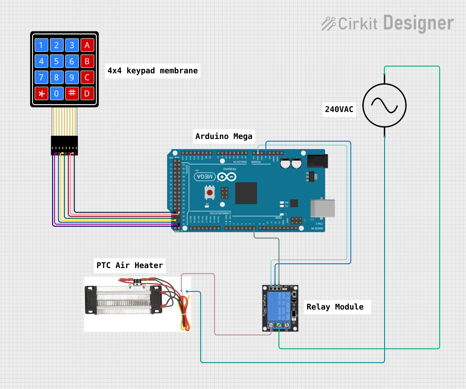
Circuit Documentation
Summary of the Circuit
This circuit is designed to interface an Arduino Mega 2560 with a 4x4 membrane matrix keypad and a 1-channel relay module. The relay module is used to control an external AC load, in this case, a PTC air heater. The Arduino Mega 2560 serves as the central processing unit, reading inputs from the keypad and controlling the relay accordingly. The AC supply is connected to the relay's common (C) terminal, and the PTC air heater is connected to the normally open (NO) terminal, allowing the Arduino to control the power to the heater.
Component List
Arduino Mega 2560
- Microcontroller board based on the ATmega2560
- It has 54 digital input/output pins (of which 15 can be used as PWM outputs), 16 analog inputs, 4 UARTs (hardware serial ports), a 16 MHz crystal oscillator, a USB connection, a power jack, an ICSP header, and a reset button.
1-Channel Relay (5V 10A)
- A relay module capable of switching up to 10A of current at AC or DC voltages.
- The module has a single relay with normally open (NO) and normally closed (NC) connections, as well as a common (C) connection.
AC SUPPLY
- Represents the AC power source for the circuit.
- Provides the necessary voltage and current to power the PTC air heater through the relay.
4X4 Membrane Matrix Keypad
- A 16-button keypad arranged in a 4x4 matrix.
- Provides user input to the Arduino Mega 2560.
PTC Air Heater
- A heating element that uses Positive Temperature Coefficient (PTC) technology for heating.
- Controlled by the relay, which is in turn controlled by the Arduino based on the keypad input.
Wiring Details
Arduino Mega 2560
- 5V pin is connected to the power pin of the 1-Channel Relay to supply operating voltage.
- GND pin is connected to the ground pin of the 1-Channel Relay to complete the power circuit.
- D7 PWM pin is connected to the signal pin of the 1-Channel Relay to control the relay operation.
- Digital pins D22, D24, D26, D28 are connected to the R1, R3, C1, C3 pins of the 4X4 Membrane Matrix Keypad respectively.
- Digital pins D23, D25, D27, D29 are connected to the R2, R4, C2, C4 pins of the 4X4 Membrane Matrix Keypad respectively.
1-Channel Relay (5V 10A)
- C (common) pin is connected to the +ve pin of the AC SUPPLY.
- NO (normally open) pin is connected to one of the terminals of the PTC air heater.
- The other terminal of the PTC air heater is connected to the -ve pin of the AC SUPPLY.
AC SUPPLY
- +ve pin is connected to the C pin of the 1-Channel Relay.
- -ve pin is connected to one of the terminals of the PTC air heater.
PTC Air Heater
- One terminal is connected to the NO pin of the 1-Channel Relay.
- The other terminal is connected to the -ve pin of the AC SUPPLY.
Documented Code
Arduino Mega 2560 Code (sketch.ino)
void setup() {
  // put your setup code here, to run once:

}

void loop() {
  // put your main code here, to run repeatedly:

}
Note: The provided code is a template and does not contain any functional code to control the relay or read inputs from the keypad. The user should implement the necessary logic within the setup() and loop() functions to read the keypad inputs and control the relay accordingly.