
ESP32-Based Smart Light Control with Potentiometer and Ambient Light Sensor
View and Edit Project In Cirkit Designer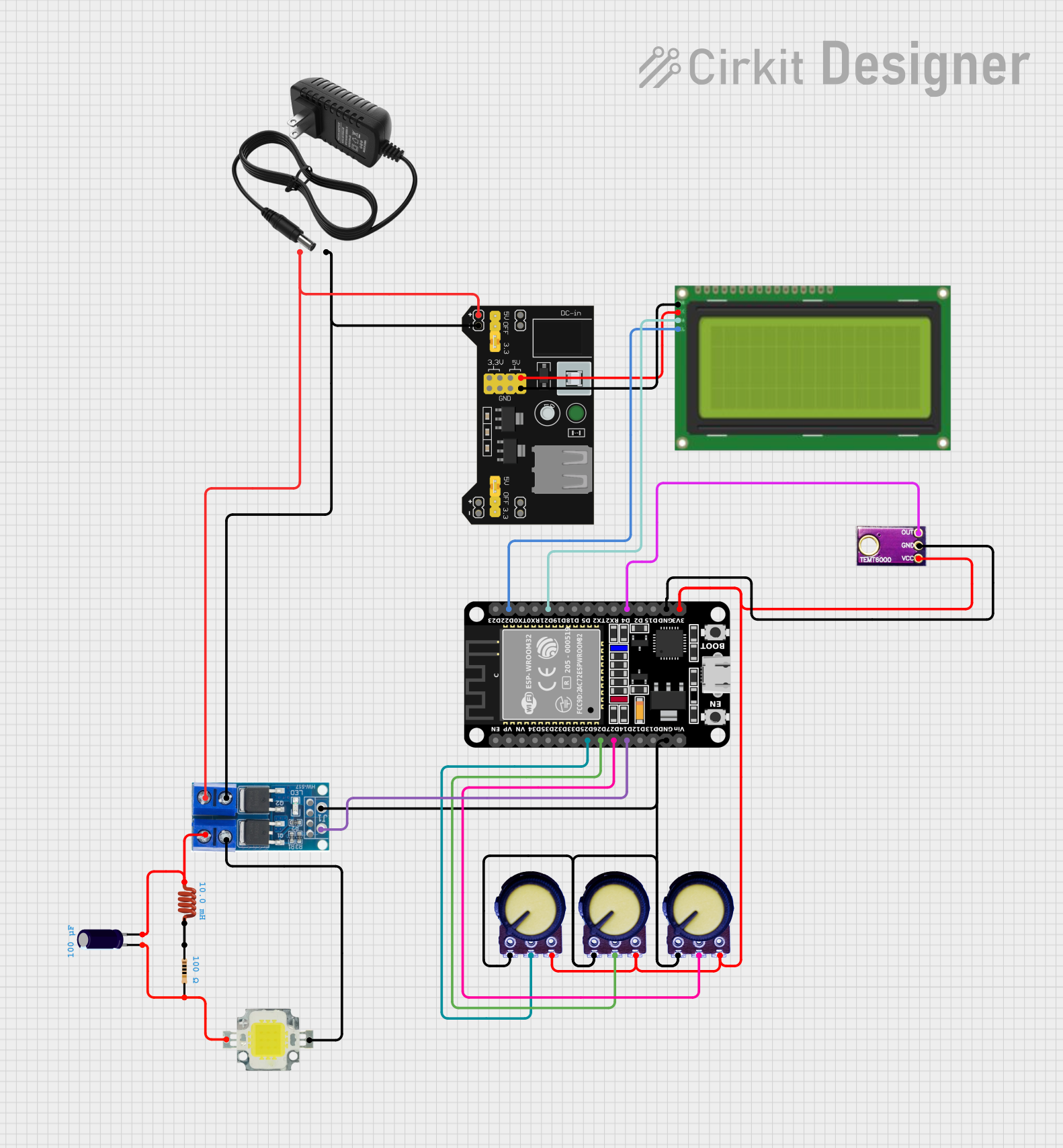
Circuit Documentation
Summary
This circuit involves an ESP32 microcontroller interfacing with various components including a power supply module, an LCD display, potentiometers, a power MOSFET, a power LED, an ambient light sensor, and passive components like resistors, inductors, and capacitors. The circuit is designed to read inputs from potentiometers and an ambient light sensor, control a power LED through a MOSFET, and display information on an LCD.
Component List
MB102 Breadboard Power Supply Module 3.3V/5V
- Pins: VCC, GND, 3.3V, 5V
- Description: Provides regulated 3.3V and 5V power supply.
ESP32 (30 pin)
- Pins: EN, VP, VN, D34, D35, D32, D33, D25, D26, D27, D14, D12, D13, GND, Vin, D23, D22, TX0, RX0, D21, D19, D18, D5, TX2, RX2, D4, D2, D15, 3V3
- Description: Microcontroller with Wi-Fi and Bluetooth capabilities.
Lcd 20x4 i2c
- Pins: GND, 5v, SCA, SCL
- Description: 20x4 character LCD display with I2C interface.
Potentiometer
- Pins: GND, Output, VCC
- Description: Variable resistor used to adjust voltage levels.
Power MOSFET
- Pins: PWM, GND, GND(5-36V), +V(5-36V)
- Description: Used to switch high power loads.
Power LED 12V 10W 0.8-0.9A
- Pins: +, -
- Description: High power LED.
Ambient Light Sensor
- Pins: GND, OUT, VCC
- Description: Measures ambient light levels.
12V Power Supply
- Pins: +, -
- Description: Provides 12V power supply.
Resistor
- Pins: pin1, pin2
- Description: 100 Ohms resistor.
Inductor
- Pins: pin 0, pin 1
- Description: 0.01 Henrys inductor.
Electrolytic Capacitor
- Pins: -, +
- Description: 0.0001 Farads capacitor.
Wiring Details
MB102 Breadboard Power Supply Module 3.3V/5V
- VCC: Connected to + of 12V Power Supply and +V(5-36V) of Power MOSFET.
- GND: Connected to - of 12V Power Supply, GND(5-36V) of Power MOSFET, GND of LCD, GND of ESP32, GND of all Potentiometers, and GND of Ambient Light Sensor.
- 5V: Connected to 5v of LCD.
ESP32 (30 pin)
- D25: Connected to Output of Potentiometer.
- D26: Connected to Output of Potentiometer.
- D27: Connected to Output of Potentiometer.
- D14: Connected to PWM of Power MOSFET.
- GND: Connected to GND of Power MOSFET, GND of all Potentiometers, and GND of Ambient Light Sensor.
- D22: Connected to SCL of LCD.
- D21: Connected to SCA of LCD.
- D4: Connected to OUT of Ambient Light Sensor.
- 3V3: Connected to VCC of all Potentiometers and VCC of Ambient Light Sensor.
Lcd 20x4 i2c
- GND: Connected to GND of MB102 Breadboard Power Supply Module.
- 5v: Connected to 5V of MB102 Breadboard Power Supply Module.
- SCA: Connected to D21 of ESP32.
- SCL: Connected to D22 of ESP32.
Potentiometer
- GND: Connected to GND of ESP32.
- Output: Connected to D25, D26, and D27 of ESP32.
- VCC: Connected to 3V3 of ESP32.
Power MOSFET
- PWM: Connected to D14 of ESP32.
- GND: Connected to GND of ESP32.
- GND(5-36V): Connected to - of 12V Power Supply and GND of Power LED.
- +V(5-36V): Connected to + of 12V Power Supply and VCC of MB102 Breadboard Power Supply Module.
Power LED 12V 10W 0.8-0.9A
- +: Connected to pin2 of Resistor.
- -: Connected to GND(5-36V) of Power MOSFET.
Ambient Light Sensor
- GND: Connected to GND of ESP32.
- OUT: Connected to D4 of ESP32.
- VCC: Connected to 3V3 of ESP32.
12V Power Supply
- +: Connected to +V(5-36V) of Power MOSFET and VCC of MB102 Breadboard Power Supply Module.
- -: Connected to GND(5-36V) of Power MOSFET and GND of MB102 Breadboard Power Supply Module.
Resistor
- pin1: Connected to pin1 of Inductor.
- pin2: Connected to + of Power LED and - of Electrolytic Capacitor.
Inductor
- pin 0: Connected to +V(5-36V) of Power MOSFET and + of Electrolytic Capacitor.
- pin 1: Connected to pin1 of Resistor.
Electrolytic Capacitor
- +: Connected to pin 0 of Inductor.
- -: Connected to pin2 of Resistor.
Code Documentation
ESP32 Code
void setup() {
  // put your setup code here, to run once:

}

void loop() {
  // put your main code here, to run repeatedly:

}
This code is a basic template for the ESP32 microcontroller. The setup() function is where you initialize your components and configurations, and the loop() function is where the main logic of your program will run repeatedly.