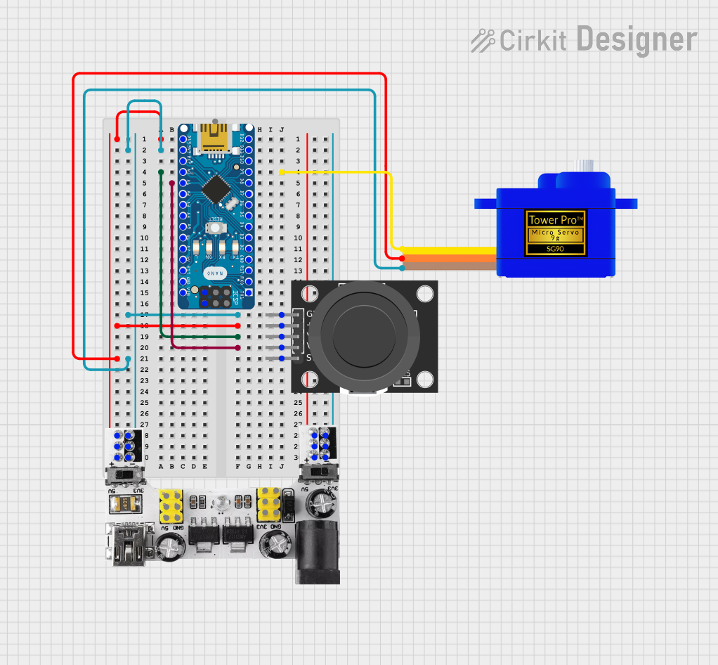
Arduino Nano Controlled Servomotor with Joystick Interface

Circuit Documentation
Summary
This circuit is designed to control a Servomotor SG90 using an Arduino Nano microcontroller, which receives input from a KY-023 Dual Axis Joystick Module. The Breadboard Power Module supplies power to the system, providing both 3.3V and 5V as required. The joystick's X and Y axis movements are read by the Arduino Nano and translated into servo motor position commands, allowing for precise control of the servo's angle.
Component List
Breadboard Power Module (3.3/5V)
- Description: A module that provides regulated 3.3V and 5V outputs from a higher voltage input.
- Pins:
+,-,VCC (5V),GND,VCC (3.3V)
Servomotor SG90
- Description: A small and lightweight servo motor suitable for a variety of hobby applications.
- Pins:
SIG,VCC,GND
KY-023 Dual Axis Joystick Module
- Description: A module that includes a two-axis joystick with a built-in pushbutton switch.
- Pins:
GND,+5V,VRx,VRy,SW
Arduino Nano
- Description: A compact microcontroller board based on the ATmega328, suitable for embedding into projects.
- Pins:
D1/TX,D0/RX,RESET,GND,D2,D3,D4,D5,D6,D7,D8,D9,D10,D11/MOSI,D12/MISO,VIN,5V,A7,A6,A5,A4,A3,A2,A1,A0,AREF,3V3,D13/SCK
Wiring Details
Breadboard Power Module (3.3/5V)
+connected to Arduino NanoD13/SCK, KY-023 Joystick Module+5V, and Servomotor SG90VCC-connected to Arduino Nano3V3, KY-023 Joystick ModuleGND, and Servomotor SG90GND
Servomotor SG90
SIGconnected to Arduino NanoD9VCCconnected to Breadboard Power Module+GNDconnected to Breadboard Power Module-
KY-023 Dual Axis Joystick Module
GNDconnected to Breadboard Power Module-+5Vconnected to Breadboard Power Module+VRxconnected to Arduino NanoA0VRyconnected to Arduino NanoA1
Arduino Nano
D13/SCKconnected to Breadboard Power Module+3V3connected to Breadboard Power Module-A0connected to KY-023 Joystick ModuleVRxA1connected to KY-023 Joystick ModuleVRyD9connected to Servomotor SG90SIG
Documented Code
#include <Servo.h>

Servo myServo;  // Create servo object

// Joystick and servo pins
const int joyXPin = A0;  // Joystick X-axis pin
const int joyYPin = A1;  // Joystick Y-axis pin
const int servoPin = 9;  // Servo control pin

// Variables to store joystick values
int joyXValue;
int joyYValue;

void setup() {
  // Start serial communication (optional)
  Serial.begin(9600);

  // Attach servo to specified pin
  myServo.attach(servoPin);
}

void loop() {
  // Read values from the joystick
  joyXValue = analogRead(joyXPin);  // Read X-axis
  joyYValue = analogRead(joyYPin);  // Read Y-axis

  // Map joystick values (0-1023) to servo angles (0-180)
  int servoAngleX = map(joyXValue, 0, 1023, 0, 180);
  int servoAngleY = map(joyYValue, 0, 1023, 0, 180);

  // Move servo based on joystick values
  myServo.write(servoAngleX);  // Move servo according to X-axis

  // Display joystick values and servo angle on Serial Monitor (optional)
  Serial.print("Joystick X: ");
  Serial.print(joyXValue);
  Serial.print(" | Servo Angle X: ");
  Serial.println(servoAngleX);

  // Delay for stability
  delay(15);
}
This code snippet is responsible for reading the analog values from the joystick's X and Y axes, mapping these values to a range suitable for servo control, and then adjusting the servo's position accordingly. The serial communication lines, which are optional, allow for monitoring the joystick's position and the corresponding servo angle through the Serial Monitor in the Arduino IDE.