
Arduino UNO RFID Access Control System with Feedback Indicators
View and Edit Project In Cirkit Designer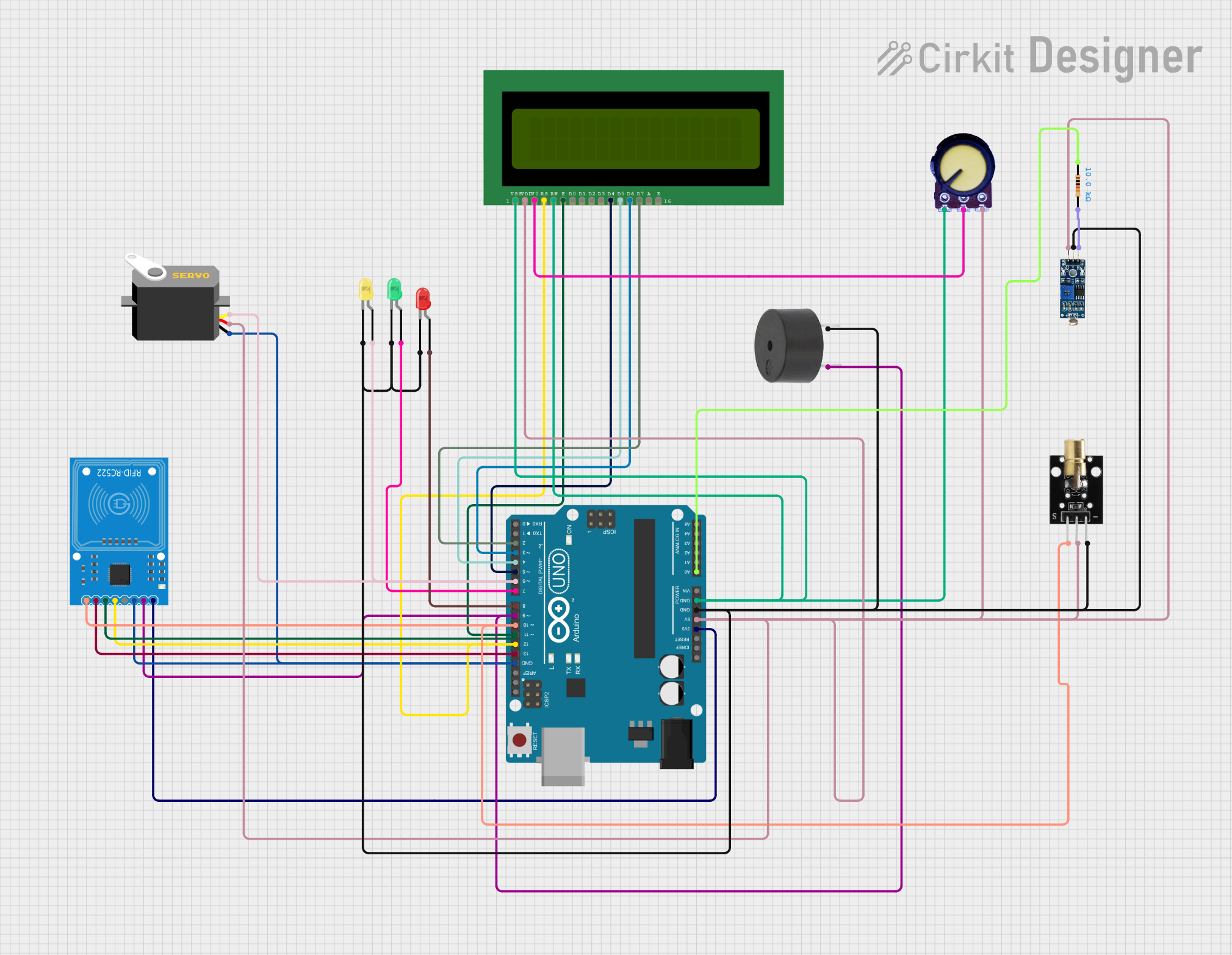
Circuit Documentation
Summary
This document provides a detailed overview of a circuit designed to interface an RFID-RC522 module with an Arduino UNO. The circuit includes various peripherals such as an LCD display, a servo motor, LEDs, a buzzer, a laser emitter, an LDR module, and a potentiometer. The Arduino UNO serves as the central microcontroller unit, controlling the interactions between the RFID reader and the other components.
Component List
RFID-RC522
- Description: An RFID module for reading RFID tags.
- Pins: SDA, SCK, MOSI, MISO, IRQ, GND, RST, 3.3V
Arduino UNO
- Description: A microcontroller board based on the ATmega328P.
- Pins: UNUSED, IOREF, Reset, 3.3V, 5V, GND, Vin, A0-A5, SCL, SDA, AREF, D0-D13
LCD 16x2 (Wokwi Compatible)
- Description: A 16x2 character LCD display compatible with Wokwi simulation.
- Pins: VSS, VDD, V0, RS, RW, E, D0-D7, A, K
Servo
- Description: A motor capable of precise angular positioning.
- Pins: gnd, vcc, pulse
LED: Two Pin (green, red, yellow)
- Description: Light Emitting Diodes of different colors.
- Pins: cathode, anode
Buzzer
- Description: An electronic buzzer for audible alerts.
- Pins: PIN, GND
KY-008 Laser Emitter
- Description: A module that emits a laser beam.
- Pins: SIG, 5v, GND
LDR Module 3 pin
- Description: A light-dependent resistor module.
- Pins: VCC, GND, DO
Potentiometer
- Description: A variable resistor with three terminals.
- Pins: GND, Output, VCC
Resistor
- Description: A passive two-terminal electrical component that implements electrical resistance.
- Pins: pin1, pin2
- Properties: Resistance: 10000 Ohms
Wiring Details
RFID-RC522
- SDA connected to Arduino UNO D10
- SCK connected to Arduino UNO D13
- MOSI connected to Arduino UNO D11 and LCD E
- MISO connected to Arduino UNO D12 and LCD RS
- IRQ not connected
- GND connected to common ground
- RST connected to Arduino UNO D9 and buzzer PIN
- 3.3V connected to Arduino UNO 3.3V
Arduino UNO
- D10 connected to RFID-RC522 SDA
- D13 connected to RFID-RC522 SCK
- D11 connected to RFID-RC522 MOSI and LCD E
- D12 connected to RFID-RC522 MISO and LCD RS
- GND connected to common ground
- 3.3V connected to RFID-RC522 3.3V
- 5V connected to common VCC
- A0 connected to Resistor pin1
- D8 connected to LED (red) anode
- D7 connected to LED (green) anode
- D6 connected to Servo pulse and LED (yellow) anode
- D5 connected to LCD D4
- D4 connected to LCD D5
- D3 connected to LCD D6
- D2 connected to LCD D7
LCD 16x2 (Wokwi Compatible)
- VSS connected to common ground
- VDD connected to common VCC
- V0 connected to Potentiometer Output
- RS connected to RFID-RC522 MISO and Arduino UNO D12
- RW connected to common ground
- E connected to RFID-RC522 MOSI and Arduino UNO D11
- D4 connected to Arduino UNO D5
- D5 connected to Arduino UNO D4
- D6 connected to Arduino UNO D3
- D7 connected to Arduino UNO D2
- A and K not connected
Servo
- gnd connected to common ground
- vcc connected to common VCC
- pulse connected to Arduino UNO D6
LED: Two Pin (green, red, yellow)
- Green LED cathode connected to common ground, anode connected to Arduino UNO D7
- Red LED cathode connected to common ground, anode connected to Arduino UNO D8
- Yellow LED cathode connected to common ground, anode connected to Arduino UNO D6
Buzzer
- PIN connected to RFID-RC522 RST and Arduino UNO D9
- GND connected to common ground
KY-008 Laser Emitter
- SIG connected to RFID-RC522 SDA
- 5v connected to common VCC
- GND connected to common ground
LDR Module 3 pin
- VCC connected to common VCC
- GND connected to common ground
- DO connected to Resistor pin2
Potentiometer
- GND connected to common ground
- Output connected to LCD V0
- VCC connected to common VCC
Resistor
- pin1 connected to Arduino UNO A0
- pin2 connected to LDR Module DO
Documented Code
void setup() {
  // put your setup code here, to run once:

}

void loop() {
  // put your main code here, to run repeatedly:

}
The provided code is a template for the Arduino UNO microcontroller. The setup() function is intended to contain initialization code that runs once, while the loop() function is meant for code that runs continuously. Specific functionality needs to be implemented within these functions to control the circuit's components based on the wiring and desired behavior.