
Arduino UNO Health Monitoring System with Wi-Fi and OLED Display
View and Edit Project In Cirkit Designer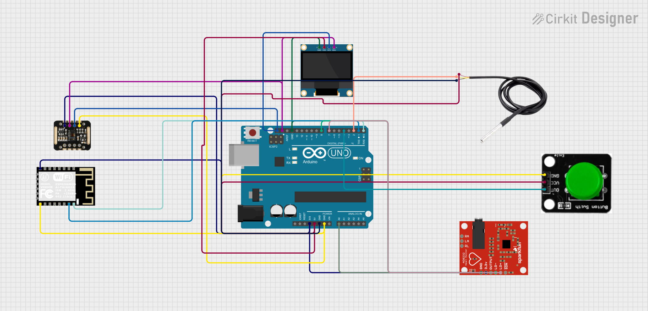
Circuit Documentation
Summary
This circuit integrates an Arduino UNO microcontroller with various sensors and modules to monitor temperature, heart rate, and SpO2 levels. It also includes a WiFi module for connectivity and an OLED display for visual output. The components are interconnected to facilitate data acquisition, processing, and display.
Component List
Arduino UNO
- Description: A microcontroller board based on the ATmega328P.
- Pins: UNUSED, IOREF, Reset, 3.3V, 5V, GND, Vin, A0, A1, A2, A3, A4, A5, SCL, SDA, AREF, D13, D12, D11, D10, D9, D8, D7, D6, D5, D4, D3, D2, D1, D0
MAX30100
- Description: Pulse oximeter and heart-rate sensor.
- Pins: VIN, SDA, SCL, GND, RD, IRD, INT
0.96" OLED
- Description: OLED display module.
- Pins: GND, VDD, SCK, SDA
DS18B20
- Description: Digital temperature sensor.
- Pins: signal, GND, vcc
ESP8266 ESP-12F WiFi Module
- Description: WiFi module for wireless communication.
- Pins: GND, GPIO15, GPIO2, GPIO0, GPIO4, GPIO5, RXD0, TXD0, RST, ADC0, EN, GPIO16, GPIO14, GPIO12, GPIO13, VCC, SCLK, MOSI, GPIO10, GPIO9, MISO, CS0
AD8232 HeartRate Monitor
- Description: Heart rate monitor sensor.
- Pins: GND, 3.3v, OUTPUT, LO-, LO+, SDN, RA, LA, RL
Green Button
- Description: Push button.
- Pins: OUT, VCC, GND
Wiring Details
Arduino UNO
3.3V connected to:
- ESP8266 ESP-12F WiFi Module (VCC)
- MAX30100 (VIN)
- AD8232 HeartRate Monitor (3.3v)
5V connected to:
- DS18B20 (vcc)
- 0.96" OLED (VDD)
- Green Button (VCC)
GND connected to:
- DS18B20 (GND)
- ESP8266 ESP-12F WiFi Module (GND)
- MAX30100 (GND)
- Green Button (GND)
- 0.96" OLED (GND)
- AD8232 HeartRate Monitor (GND)
A0 connected to:
- AD8232 HeartRate Monitor (OUTPUT)
SCL connected to:
- 0.96" OLED (SCK)
- MAX30100 (SCL)
SDA connected to:
- 0.96" OLED (SDA)
- MAX30100 (SDA)
D8 connected to:
- AD8232 HeartRate Monitor (LO-)
D7 connected to:
- AD8232 HeartRate Monitor (LO+)
D4 connected to:
- Green Button (OUT)
D2 connected to:
- DS18B20 (signal)
D1 connected to:
- ESP8266 ESP-12F WiFi Module (RXD0)
D0 connected to:
- ESP8266 ESP-12F WiFi Module (TXD0)
MAX30100
VIN connected to:
- Arduino UNO (3.3V)
SDA connected to:
- Arduino UNO (SDA)
SCL connected to:
- Arduino UNO (SCL)
GND connected to:
- Arduino UNO (GND)
0.96" OLED
VDD connected to:
- Arduino UNO (5V)
SCK connected to:
- Arduino UNO (SCL)
SDA connected to:
- Arduino UNO (SDA)
GND connected to:
- Arduino UNO (GND)
DS18B20
vcc connected to:
- Arduino UNO (5V)
GND connected to:
- Arduino UNO (GND)
signal connected to:
- Arduino UNO (D2)
ESP8266 ESP-12F WiFi Module
VCC connected to:
- Arduino UNO (3.3V)
GND connected to:
- Arduino UNO (GND)
RXD0 connected to:
- Arduino UNO (D1)
TXD0 connected to:
- Arduino UNO (D0)
AD8232 HeartRate Monitor
3.3v connected to:
- Arduino UNO (3.3V)
GND connected to:
- Arduino UNO (GND)
OUTPUT connected to:
- Arduino UNO (A0)
LO- connected to:
- Arduino UNO (D8)
LO+ connected to:
- Arduino UNO (D7)
Green Button
VCC connected to:
- Arduino UNO (5V)
GND connected to:
- Arduino UNO (GND)
OUT connected to:
- Arduino UNO (D4)
Code Documentation
#include <Wire.h>
#include <Adafruit_SSD1306.h>
#include <Adafruit_GFX.h>
#include <OneWire.h>
#include <DallasTemperature.h>
#include <MAX30100_PulseOximeter.h>

#define SCREEN_WIDTH 128
#define SCREEN_HEIGHT 64
#define OLED_RESET -1
Adafruit_SSD1306 display(SCREEN_WIDTH, SCREEN_HEIGHT, &Wire, OLED_RESET);

#define ONE_WIRE_BUS 2
OneWire oneWire(ONE_WIRE_BUS);
DallasTemperature sensors(&oneWire);

#define BUTTON_PIN 4
#define ECG_PIN A0
#define LO_PLUS_PIN 7
#define LO_MINUS_PIN 8

PulseOximeter pox;

void setup() {
  Serial.begin(115200);
  pinMode(BUTTON_PIN, INPUT);
  pinMode(LO_PLUS_PIN, INPUT);
  pinMode(LO_MINUS_PIN, INPUT);
  display.begin(SSD1306_SWITCHCAPVCC, 0x3C);
  display.display();
  delay(2000);
  display.clearDisplay();
  sensors.begin();
  pox.begin();
}

void loop() {
  sensors.requestTemperatures();
  float temperature = sensors.getTempCByIndex(0);
  pox.update();
  float heartRate = pox.getHeartRate();
  float SpO2 = pox.getSpO2();
  int ecgValue = analogRead(ECG_PIN);
  bool loPlus = digitalRead(LO_PLUS_PIN);
  bool loMinus = digitalRead(LO_MINUS_PIN);
  display.clearDisplay();
  display.setTextSize(1);
  display.setTextColor(SSD1306_WHITE);
  display.setCursor(0, 0);
  display.print("Temp: ");
  display.print(temperature);
  display.println(" C");
  display.print("HR: ");
  display.print(heartRate);
  display.println(" bpm");
  display.print("SpO2: ");
  display.print(SpO2);
  display.println(" %");
  display.print("ECG: ");
  display.println(ecgValue);
  display.print("LO+: ");
  display.println(loPlus);
  display.print("LO-: ");
  display.println(loMinus);
  display.display();
  delay(1000);
}
This code initializes the sensors and display, reads data from the sensors, and displays the data on the OLED screen. The loop continuously updates the display with the latest sensor readings.