Cirkit Designer
Your all-in-one circuit design IDE
Home /
Project Documentation
Arduino-Controlled Robotic Vehicle with Flame Detection and Obstacle Avoidance

Circuit Documentation
Summary
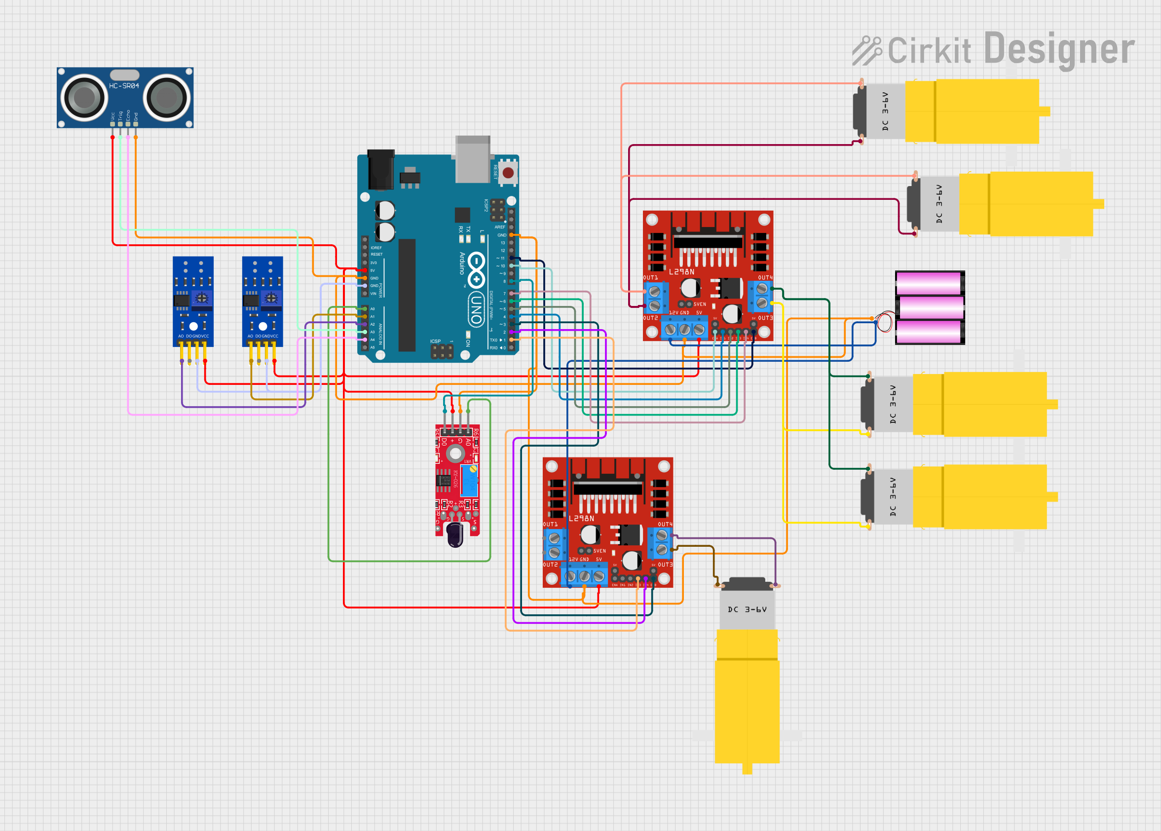
This circuit is designed to control a set of DC motors using an L298N motor driver, interfaced with an Arduino UNO microcontroller. The circuit includes sensors for detecting flames and lines, as well as an ultrasonic sensor for distance measurement. The Arduino UNO reads sensor data and controls the motor driver to navigate the environment based on sensor inputs. The circuit is powered by a 12V battery, which also supplies power to the motor driver.
Component List
L298N DC Motor Driver
- Description: A motor driver module capable of driving two DC motors.
- Pins: OUT1, OUT2, 12V, GND, 5V, OUT3, OUT4, 5V-ENA-JMP-I, 5V-ENA-JMP-O, +5V-J1, +5V-J2, ENA, IN1, IN2, IN3, IN4, ENB
Motor Amarillo Motorreductor Hobby
- Description: A yellow DC gear motor.
- Pins: vcc, GND
Arduino UNO
- Description: A microcontroller board based on the ATmega328P.
- Pins: UNUSED, IOREF, Reset, 3.3V, 5V, GND, Vin, A0, A1, A2, A3, A4, A5, SCL, SDA, AREF, D13, D12, D11, D10, D9, D8, D7, D6, D5, D4, D3, D2, D1, D0
Battery 12V
- Description: A 12V power source for the circuit.
- Pins: +, -
KY-026 Flame Sensor
- Description: A sensor module for detecting flames.
- Pins: A0, GND, VCC, D0
HC-SR04 Ultrasonic Sensor
- Description: A sensor for measuring distance via ultrasonic waves.
- Pins: VCC, TRIG, ECHO, GND
KY-033 Line Tracking Sensor
- Description: A sensor for detecting lines on the ground.
- Pins: A0, D0, GND, VCC
Wiring Details
L298N DC Motor Driver
- 5V: Connected to the 5V output of the Arduino UNO and other 5V sensors.
- GND: Connected to the GND of the battery, Arduino UNO, and other GND sensors.
- 12V: Connected to the + of the 12V battery.
- ENA, ENB: Control signals from Arduino UNO (D10, D11).
- IN1, IN2, IN3, IN4: Control signals from Arduino UNO (D4, D5, D6, D7 for one driver; D1, D2 for the other driver).
Motor Amarillo Motorreductor Hobby
- vcc: Connected to the OUT1/OUT3 of the L298N motor driver.
- GND: Connected to the OUT2/OUT4 of the L298N motor driver.
Arduino UNO
- 5V: Supplies power to the 5V line of the circuit.
- GND: Common ground for the circuit.
- A0, A1, A2, A3, A4: Sensor inputs from flame sensor and line tracking sensors, and ultrasonic sensor.
- D4, D5, D6, D7, D10, D11: Outputs to control the L298N motor driver.
- D8: Input from the flame sensor's digital output.
Battery 12V
- +: Supplies power to the 12V input of the L298N motor driver.
- -: Connected to the common ground of the circuit.
KY-026 Flame Sensor
- VCC: Connected to the 5V line.
- GND: Connected to the common ground.
- A0: Analog output connected to Arduino UNO A0.
- D0: Digital output connected to Arduino UNO D8.
HC-SR04 Ultrasonic Sensor
- VCC: Connected to the 5V line.
- GND: Connected to the common ground.
- TRIG: Trigger pin connected to Arduino UNO A3.
- ECHO: Echo pin connected to Arduino UNO A4.
KY-033 Line Tracking Sensor
- VCC: Connected to the 5V line.
- GND: Connected to the common ground.
- A0: Analog output connected to Arduino UNO A1 or A2.
Documented Code
// Pin definitions
const int ENA = 10;
const int ENB = 11;
const int IN1 = 4;
const int IN2 = 5;
const int IN3 = 6;
const int IN4 = 7;
const int TRIG = A3;
const int ECHO = A4;
const int FLAME_D0 = 8;
const int FLAME_A0 = A0;
const int LINE1 = A1;
const int LINE2 = A2;

void setup() {
  // Initialize motor driver pins as outputs
  pinMode(ENA, OUTPUT);
  pinMode(ENB, OUTPUT);
  pinMode(IN1, OUTPUT);
  pinMode(IN2, OUTPUT);
  pinMode(IN3, OUTPUT);
  pinMode(IN4, OUTPUT);
  // Initialize sensor pins
  pinMode(TRIG, OUTPUT);
  pinMode(ECHO, INPUT);
  pinMode(FLAME_D0, INPUT);
  pinMode(LINE1, INPUT);
  pinMode(LINE2, INPUT);
  Serial.begin(9600);
}

void loop() {
  // Read sensors
  int flameDetected = digitalRead(FLAME_D0);
  int line1 = analogRead(LINE1);
  int line2 = analogRead(LINE2);
  int distance = getDistance();

  // Check for white line and flame
  if ((line1 > 500 || line2 > 500) && (flameDetected == LOW)) {
    stopMotors();
    return;
  }

  // Check for walls
  if (distance < 20) {
    avoidWall();
    return;
  }

  // Check for flame
  if (flameDetected == LOW) {
    moveForward();
  } else {
    // If no flame is detected, keep searching
    searchForFlame();
  }
}

void moveForward() {
  digitalWrite(IN1, HIGH);
  digitalWrite(IN2, LOW);
  analogWrite(ENA, 128); // 50% duty cycle
  digitalWrite(IN3, HIGH);
  digitalWrite(IN4, LOW);
  analogWrite(ENB, 128); // 50% duty cycle
}

void stopMotors() {
  analogWrite(ENA, 0);
  analogWrite(ENB, 0);
}

void avoidWall() {
  // Simple wall avoidance: stop and turn
  stopMotors();
  delay(500);
  digitalWrite(IN1, LOW);
  digitalWrite(IN2, HIGH);
  analogWrite(ENA, 128); // 50% duty cycle
  digitalWrite(IN3, HIGH);
  digitalWrite(IN4, LOW);
  analogWrite(ENB, 128); // 50% duty cycle
  delay(1000);
  stopMotors();
  delay(500);
}

void searchForFlame() {
  // Simple search pattern: rotate in place
  digitalWrite(IN1, HIGH);
  digitalWrite(IN2, LOW);
  analogWrite(ENA, 128); // 50% duty cycle
  digitalWrite(IN3, LOW);
  digitalWrite(IN4, HIGH);
  analogWrite(ENB, 128); // 50% duty cycle
}

int getDistance() {
  digitalWrite(TRIG, LOW);
  delayMicroseconds(2);
  digitalWrite(TRIG, HIGH);
  delayMicroseconds(10);
  digitalWrite(TRIG, LOW);
  long duration = pulseIn(ECHO, HIGH);
  int distance = duration * 0.034 / 2;
  return distance;
}
This code is responsible for controlling the motors based on sensor inputs. It includes functions for moving forward, stopping the motors, avoiding walls, and searching for flames. The getDistance function calculates the distance to an object using the ultrasonic sensor.